DEFINE THE PROBLEM

You need to begin the solution to a design problem with a clear, unambiguous definition of the problem. Unlike an analysis problem, a design problem often begins as a vague, abstract idea in the mind of the designer. Creating a clear definition of a design problem is more difficult than, defining an analysis problem. The definition of a design problem may evolve through a series of steps or processes as you develop a more complete understanding of the problem.


Identify and Establish the Need
Engineering design activity always occurs in response to a human need. Before you can develop a problem definition statement for a design problem, you need to recognize the need for a new product, system, or machine. Thomas Newcomen saw the need for a machine to pump the water from the bottom of coal mines in England. Recognizing this human need provided him the stimulus for designing the first steam engine in 1712.
Before engineers can clearly define a design problem, they must see and understand this need.

Although engineers are generally involved in defining the problem, they may not be the ones who initially recognize the need. In private industry, market forces generally establish the need for a new design. A company's survival depends on producing a product that people will buy and can be manufactured and sold at a profit. Ultimately, consumers establish a need, because they will purchase and use a product that they
perceive as meeting a need for comfort, health, recreation, transportation, shelter, and so on. Likewise, the citizens of a government decide whether they need safe drinking water, roads and highways, libraries, schools, fire protection, and so on.

The perceived need, however, may not be the real need. Before you delve into the details of producing a solution, you need to make sure you have enough information to generate a clear, unambiguous problem definition that addresses the real need. The following example illustrates the importance of understanding the need before attempting a solution.

Example: Automobile Airbag Inflation - How Not to Solve a Problem
A company that manufactures automobile airbags has a problem with an unacceptably high rate of failure in the inflation of the bag. During testing, 10 percent of the bags do not fully inflate. An engineer is assigned the job of solving the problem. At first the engineer defines the problem as a failure in the materials and construction of the inflation device. The engineer begins to solve this problem by producing a more robust inflation device. After considerable effort, the engineer discovers that improving the inflation device does not change the failure rate in the bags. Eventually, this engineer re-examines the initial definition of the problem. The company investigates the airbag inflation  problem further and discovers that a high degree of variability in the tightness of folds is
responsible for the failure of some bags to inflate. At the time the bags were folded and packed by people on an assembly line. With a more complete understanding of the need, the engineer redefined the problem as one of increasing the consistency in tightness of the folds in the bags. The final solution to this problem is a machine that automatically folds the bags.

Often the apparent need is not the real need. A common tendency is to begin generating a solution to an apparent problem without understanding the problem. This approach is exactly the wrong way to begin solving a problem such as this. You would be generating solutions to a problem that has never been defined.
People have a natural tendency to attack the current solution to a problem rather than the problem itself. Attacking a current solution may eliminate inadequacies but will not produce a creative and innovative solution. For example, the engineer at the airbag company could have only looked at the current method for folding airbags-using humans on an assembly line. The engineer might have solved the problem with inconsistent tightness by modifying the assembly line procedure. However, the final solution to the problem proved to be more cost effective and reliable, in addition to producing a superior consistency in the tightness of the folds.


  • READ MORE.......


  • ENGINEERING DESIGN PROCESS
    Education Transfer Plan
    Prepared by
    Seyyed Khandani, Ph.D.
    skhandani@dvc.edu


    for STEP BY STEP GUIDE illustrator simple tutorial please visit.........
    www.illustratorsimpletutorial.blogspot.com

    ---or---

  • www.illustrator-simple-tutorial.com


  • THE DESIGN PROCESS

    The basic five-step process usually used in a problem-solving works for design problems as well. Since design problems are usually defined more vaguely and have a multitude of correct answers, the process may require backtracking and iteration. Solving a design problem is a contingent process and the solution is subject to unforeseen complications and changes as it develops. Until the Wright brothers actually built and tested their early gliders, they did not know the problems and difficulties they would face controlling a powered plane.


    The five steps used for solving design problems are:
    1. Define the problem
    2. Gather pertinent information
    3. Generate multiple solutions
    4. Analyze and select a solution
    5. Test and implement the solution
    The first step in the design process is the problem definition. This definition usually contains a listing of the product or customer requirements and specially information about product functions and features among other things. In the next step, relevant information for the design of the product and its functional specifications is obtained. A survey regarding the availability of similar products in the market should be performed at this stage. Once the details of the design are clearly identified, the design team with inputs from test, manufacturing, and marketing teams generates multiple alternatives to achieve the goals and the requirements of the design. Considering cost, safety, and other criteria for selection, the more promising alternatives are selected for further analysis.
    Detail design and analysis step enables a complete study of the solutions and result in identification of the final design that best fits the product requirements. Following this step, a prototype of the design is constructed and functional tests are performed to verify and possibly modify the design.
    When solving a design problem, you may find at any point in the process that you need to go back to a previous step. The solution you chose may prove unworkable for any number of reasons and may require redefining the problem, collecting more information, or generating different solutions. This continuous iterative process is represented in the following Figure.
    This document intends to clarify some of the details involved in implementing the design process. Therefore a description of the details involved in each step of the design process is listed below. Although the descriptions of the activities within each step may give the impression that the steps are sequential and independent from each other, the iterative nature of the application of the process should be kept in mind throughout the document.


    ENGINEERING DESIGN PROCESS
    Education Transfer Plan
    Prepared by
    S
  • Read more........
  • ENGINEERING DESIGN

    Most engineering designs can be classified as inventions-devices or systems that are
    created by human effort and did not exist before or are improvements over existing
    devices or systems. Inventions, or designs, do not suddenly appear from nowhere. They are the result of bringing together technologies to meet human needs or to solve problems. Sometimes a design is the result of someone trying to do a task more quickly or efficiently. Design activity occurs over a period of time and requires a step-by-step methodology.

    We described engineers primarily as problem solvers. What distinguishes design from other types of problem solving is the nature of both the problem and the solution. Design problems are open ended in nature, which means they have more than one correct solution. The result or solution to a design problem is a system that possesses specified properties.

    Design problems are usually more vaguely defined than analysis problems. Suppose that you are asked to determine the maximum height of a snowball given an initial velocity and release height. This is an analysis problem because it has only one answer. If you change the problem statement to read, "Design a device to launch a 1-pound snowball to a height of at least 160 feet," this analysis problem becomes a design problem. The solution to the design problem is a system having specified properties (able to launch a snowball 160 feet), whereas the solution to the analysis problem consisted of the properties of a given system (the height of the snowball). The solution to a design problem is therefore open ended, since there are many possible devices that can launch a snowball to a given height. The original problem had a single solution: the maximum
    height of the snowball, determined from the specified initial conditions.
    Solving design problems is often an iterative process: As the solution to a design problem evolves, you find yourself continually refining the design. While implementing the solution to a design problem, you may discover that the solution you've developed is unsafe, too expensive, or will not work. You then "go back to the drawing board" and modify the solution until it meets your requirements. For example, the Wright brothers'
    airplane did not fly perfectly the first time. They began a program for building an airplane by first conducting tests with kites and then gliders. Before attempting powered flight, they solved the essential problems of controlling a plane's motion in rising, descending, and turning. They didn't construct a powered plane until after making more than 700 successful glider flights. Design activity is therefore cyclic or iterative in nature, whereas
    analysis problem solving is primarily sequential.
    The solution to a design problem does not suddenly appear in a vacuum. A good solution requires a methodology or process. There are probably as many processes of design as there are engineers. Therefore, this lesson does not present a rigid "cookbook" approach to design but presents a general application of the five-step problem-solving methodology associated with the design process. The process described here is general, and you can adapt it to the particular problem you are trying to solve


    ENGINEERING DESIGN PROCESS
    Education Transfer Plan
    Prepared by
    Seyyed Khandani, Ph.D.


  • Read more........
  • Design Considerations

    Sometimes the strength required of an element in a system is an important factor in the determination of the geometry and the dimensions of the element. In such a situation we say that strength is an important design consideration. When we use the expression design consideration, we are referring to some characteristic that influences the design of the element or, perhaps, the entire system. Usually quite a number of such characteristics must be considered and prioritized in a given design situation. Many of the important ones are as follows (not necessarily in order of importance):
    1 Functionality
    2 Strength/stress
    3 Distortion/deflection/stiffness
    4 Wear
    5 Corrosion
    6 Safety
    7 Reliability
    8 Manufacturability
    9 Utility
    10 Cost
    11 Friction
    12 Weight
    13 Life
    14 Noise
    15 Styling
    16 Shape
    17 Size
    18 Control
    19 Thermal properties
    20 Surface
    21 Lubrication
    22 Marketability
    23 Maintenance
    24 Volume
    25 Liability
    26 Remanufacturing/resource recovery

    Some of these characteristics have to do directly with the dimensions, the material, the processing, and the joining of the elements of the system. Several characteristics may be interrelated, which affects the configuration of the total system.


    Mechanical Engineering
    McGraw−Hill Primis
    ISBN: 0−390−76487−6
    Text:
    Shigley’s Mechanical Engineering Design,
    Eighth Edition
    Budynas−Nisbett
    Shigley’s Mechanical Engineering Design,
    Eighth Edition
    Budynas−Nisbett


  • Read more........
  • Phases and Interactions of the Design Process

    What is the design process? How does it begin? Does the engineer simply sit down at a desk with a blank sheet of paper and jot down some ideas? What happens next? What factors influence or control the decisions that have to be made? Finally, how does the design process end?
    The complete design process, from start to finish, is often outlined as in Fig. 1–1. The process begins with an identification of a need and a decision to do something about it. After many iterations, the process ends with the presentation of the plans for satisfying the need. Depending on the nature of the design task, several design phases may be repeated throughout the life of the product, from inception to termination.
    In the next several subsections, we shall examine these steps in the design process in detail. Identification of need generally starts the design process. Recognition of the need and phrasing the need often constitute a highly creative act, because the need may be only a vague discontent, a feeling of uneasiness, or a sensing that something is not right.The need is often not evident at all; recognition is usually triggered by a particular adverse circumstance or a set of random circumstances that arises almost simultaneously. 
    For example, the need to do something about a food-packaging machine may be indicated by the noise level, by a variation in package weight, and by slight but perceptible variations in the quality of the packaging or wrap.
    There is a distinct difference between the statement of the need and the definition of the problem. The definition of problem is more specific and must include all the specifications for the object that is to be designed. The specifications are the input and output quantities, the characteristics and dimensions of the space the object must occupy, and all the limitations on these quantities. We can regard the object to be designed as something in a black box. In this case we must specify the inputs and outputs of the box,
    together with their characteristics and limitations. The specifications define the cost, the number to be manufactured, the expected life, the range, the operating temperature, and the reliability. Specified characteristics can include the speeds, feeds, temperature limitations, maximum range, expected variations in the variables, dimensional and weight limitations, etc.

    There are many implied specifications that result either from the designer’s particular environment or from the nature of the problem itself. The manufacturing processes that are available, together with the facilities of a certain plant, constitute restrictions on a designer’s freedom, and hence are a part of the implied specifications.
    It may be that a small plant, for instance, does not own cold-working machinery.
    Knowing this, the designer might select other metal-processing methods that can be performed in the plant. The labor skills available and the competitive situation also constitute implied constraints. Anything that limits the designer’s freedom of choice is a constraint. Many materials and sizes are listed in supplier’s catalogs,
    for instance, but these are not all easily available and shortages frequently occur.
    Furthermore, inventory economics requires that a manufacturer stock a minimum number of materials and sizes. An example of a specification is given in Sec. 1–16. This example is for a case study of a power transmission that is presented throughout this text.
    The synthesis of a scheme connecting possible system elements is sometimes called the invention of the concept or concept design. This is the first and most important step in the synthesis task. Various schemes must be proposed, investigated, and quantified in terms of established metrics.1 As the fleshing out of the scheme progresses, analyses must be performed to assess whether the system performance is satisfactory or
    better, and, if satisfactory, just how well it will perform. System schemes that do not survive analysis are revised, improved, or discarded. Those with potential are optimized to determine the best performance of which the scheme is capable. Competing schemes are compared so that the path leading to the most competitive product can be chosen. Figure 1–1 shows that synthesis and analysis and optimization are intimately and iteratively related.

    We have noted, and we emphasize, that design is an iterative process in which we proceed through several steps, evaluate the results, and then return to an earlier phase of the procedure. Thus, we may synthesize several components of a system, analyze and optimize them, and return to synthesis to see what effect this has on the remaining parts of the system. For example, the design of a system to transmit power requires attention
    to the design and selection of individual components (e.g., gears, bearings, shaft).
    However, as is often the case in design, these components are not independent. In order to design the shaft for stress and deflection, it is necessary to know the applied forces. If the forces are transmitted through gears, it is necessary to know the gear specifications in order to determine the forces that will be transmitted to the shaft. But stock gears come with certain bore sizes, requiring knowledge of the necessary shaft diameter.
    Clearly, rough estimates will need to be made in order to proceed through the process, refining and iterating until a final design is obtained that is satisfactory for each individual component as well as for the overall design specifications. Throughout the text we will elaborate on this process for the case study of a power  transmission design.
    Both analysis and optimization require that we construct or devise abstract models of the system that will admit some form of mathematical analysis. We call these models mathematical models. In creating them it is our hope that we can find one that will simulate the real physical system very well. As indicated in Fig. 1–1, evaluation is a significant phase of the total design process. Evaluation is the final proof of a successful
    design and usually involves the testing of a prototype in the laboratory. Here we wish to discover if the design really satisfies the needs. Is it reliable? Will it compete successfully with similar products? Is it economical to manufacture and to use? Is it easily maintained and adjusted? Can a profit be made from its sale or use? How likely is it to result in product-liability lawsuits? And is insurance easily and cheaply obtained? Is it likely that recalls will be needed to replace defective parts or systems?
    Communicating the design to others is the final, vital presentation step in the design process. Undoubtedly, many great designs, inventions, and creative works have been lost to posterity simply because the originators were unable or unwilling to explain their accomplishments to others. Presentation is a selling job. The engineer,
    when presenting a new solution to administrative, management, or supervisory persons, is attempting to sell or to prove to them that this solution is a better one. Unless this can be done successfully, the time and effort spent on obtaining the solution have been largely wasted. When designers sell a new idea, they also sell themselves. If they are repeatedly successful in selling ideas, designs, and new solutions to management, they
    begin to receive salary increases and promotions; in fact, this is how anyone succeeds in his or her profession.


    Mechanical Engineering
    McGraw−Hill Primis
    ISBN: 0−390−76487−6
    Text:
    Shigley’s Mechanical Engineering Design,
    Eighth Edition
    Budynas−Nisbett
    Shigley’s Mechanical Engineering Design,
    Eighth Edition
    Budynas−Nisbett


  • Read more........
  • Grey cast iron.

    It is an ordinary commercial iron having the following compositions :
    Carbon = 3 to 3.5%; Silicon = 1 to 2.75%; Manganese = 0.40 to 1.0%; Phosphorous = 0.15 to 1% ; Sulphur = 0.02 to 0.15% ; and the remaining is iron.
    The grey colour is due to the fact that the carbon is present in the form of *free graphite. It has a low tensile strength, high compressive strength and no ductility. It can be easily machined. A very good property of grey cast iron is that the free graphite in its structure acts as a lubricant. Due to this reason, it is very suitable for those parts where sliding action is desired. The grey iron castings are widely used for machine tool bodies, automotive cylinder blocks, heads, housings, fly-wheels, pipes and pipe fittings and agricultural implements.
    According to Indian standard specifications (IS: 210 – 1993), the grey cast iron is designated by the alphabets ‘FG’ followed by a figure indicating the minimum tensile strength in MPa or N/mm2.
    For example, ‘FG 150’ means grey cast iron with 150 MPa or N/mm2 as minimum tensile strength. The seven recommended grades of grey cast iron with their tensile strength and Brinell hardness number (B.H.N) are given in Table 2.3.


    A TEXTBOOK OF Machine Design (S.I. UNITS)
    [A Textbook for the Students of B.E. / B.Tech., U.P.S.C. (Engg. Services); Section ‘B’ of A.M.I.E. (I)]

    R.S. KHURMI
    J.K. GUPTA

    2005
    EURASIA PUBLISHING HOUSE (PVT.) LTD.
    RAM NAGAR, NEW DELHI-110 055


  • Read more........
  • Mechanical Engineering Design

    Mechanical engineers are associated with the production and processing of energy and
    with providing the means of production, the tools of transportation, and the techniques of automation. The skill and knowledge base are extensive. Among the disciplinary bases are mechanics of solids and fluids, mass and momentum transport, manufacturing processes, and electrical and information theory. Mechanical engineering design involves all the disciplines of mechanical engineering.
    Real problems resist compartmentalization. A simple journal bearing involves fluid
    flow, heat transfer, friction, energy transport, material selection, hermomechanical
    treatments, statistical descriptions, and so on. A building is environmentally controlled.
    The heating, ventilation, and air-conditioning considerations are sufficiently specialized that some speak of heating, ventilating, and air-conditioning design as if it is separate and distinct from mechanical engineering design. Similarly, internal-combustion engine design, turbomachinery design, and jet-engine design are sometimes considered discrete entities. Here, the leading string of words preceding the word design is merely a product descriptor. Similarly, there are phrases such as machine design, machine-element design, machine-component design, systems design, and fluid-power design. All of these phrases are somewhat more focused examples of mechanical engineering design. They all draw on the same bodies of knowledge, are similarly organized, and require similar skills.


    Mechanical Engineering
    McGraw−Hill Primis
    ISBN: 0−390−76487−6
    Text:
    Shigley’s Mechanical Engineering Design,
    Eighth Edition
    Budynas−Nisbett
    Shigley’s Mechanical Engineering Design,
    Eighth Edition
    Budynas−Nisbett
    McGraw -Hill


  • Read more........
  • Cast Iron

    The cast iron is obtained by re-melting pig iron with coke and limestone in a furnace known as cupola.
    It is primarily an alloy of iron and carbon. The carbon contents in cast iron varies from 1.7 per cent to 4.5 per cent. It also contains small amounts of silicon,
    manganese, phosphorous and sulphur. The carbon in a cast iron is present in either of the following two forms:
    1. Free carbon or graphite, and 2. Combined carbon or cementite.
    Since the cast iron is a brittle material, therefore, it cannot be used in those parts of machines which are subjected to shocks. The properties of cast iron which
    make it a valuable material for engineering purposes are its low cost, good casting characteristics, high compressive strength, wear resistance and excellent machinability. The compressive strength of cast iron is much greater than the tensile strength. Following are the values of ultimate strength of cast iron :
    Tensile strength = 100 to 200 MPa*
    Compressive strength = 400 to 1000 MPa
    Shear strength = 120 MPa

    (1MPa = 1MN/m2 = 1 × 10⁶ N/m2 = 1 N/mm2)


    A TEXTBOOK OF Machine Design (S.I. UNITS)
    [A Textbook for the Students of B.E. / B.Tech., U.P.S.C. (Engg. Services); Section ‘B’ of A.M.I.E. (I)]

    R.S. KHURMI
    J.K. GUPTA

    2005
    EURASIA PUBLISHING HOUSE (PVT.) LTD.
    RAM NAGAR, NEW DELHI-110 055


  • Read more........
  • Mechanical Properties of Metals

    The mechanical properties of the metals are those which are associated with the ability of the material to resist mechanical forces and load. These  mechanical properties of the metal include strength, stiffness, elasticity, plasticity, ductility, brittleness, malleability, toughness, resilience, creep and
    hardness. We shall now discuss these properties as follows:
    1. Strength. It is the ability of a material to resist the externally applied forces without breaking or yielding. The internal resistance offered by a part to an externally applied force is called *stress.
    2. Stiffness. It is the ability of a material to resist deformation under stress. The modulus of elasticity is the measure of stiffness.
    3. Elasticity. It is the property of a material to regain its original shape after deformation when the external forces are removed. This property is desirable for materials used in tools and machines. It may be noted that steel is more elastic than rubber.
    4. Plasticity. It is property of a material which retains the deformation produced under load permanently. This property of the material is necessary for forgings, in stamping images on coins and in ornamental work.
    5. Ductility. It is the property of a material enabling it to be drawn into wire with the application of a tensile force. A ductile material must be both strong and plastic. The ductility is usually measured by the terms, percentage elongation and percentage reduction in area. The ductile material commonly used in engineering practice (in order of diminishing ductility) are mild steel, copper, aluminium, nickel, zinc, tin and lead.
    Note : The ductility of a material is commonly measured by means of percentage elongation and percentage
    reduction in area in a tensile test. (Refer Chapter 4, Art. 4.11).
    6. Brittleness. It is the property of a material opposite to ductility. It is the property of breaking of a material with little permanent distortion. Brittle materials when subjected to tensile loads, snap off without giving any sensible elongation. Cast iron is a brittle material.
    7. Malleability. It is a special case of ductility which permits materials to be rolled or hammered into thin sheets. A malleable material should be plastic but it is not essential to be so strong. The malleable materials commonly used in engineering practice (in order of diminishing malleability) are lead, soft steel, wrought iron, copper and aluminium.
    8. Toughness. It is the property of a material to resist fracture due to high impact loads like hammer blows. The toughness of the material decreases when it is heated. It is measured by the amount of energy that a unit volume of the material has absorbed after being stressed upto the point of fracture. This property is desirable
    in parts subjected to shock and impact loads.
    9. Machinability. It is the property of a material which refers to a relative case with which a material can be cut. The machinability of a material can be measured in a number of ways such as comparing the tool life for cutting different materials or thrust required to remove the material at some given rate or the energy required to remove a unit volume of the material. It may be noted that brass can be easily machined than steel.
    10. Resilience. It is the property of a material to absorb energy and to resist shock and impact loads. It is measured by the amount of energy absorbed per unit volume within elastic limit. This property is essential for
    spring materials.
    11. Creep. When a part is subjected to a constant stress at high temperature for a long period of time, it will undergo a slow and permanent deformation called creep. This property is considered in designing internal
    combustion engines, boilers and turbines.
    12. Fatigue. When a material is subjected to repeated stresses, it fails at stresses below the yield point stresses. Such type of failure of a material is known as *fatigue. The failure is caused by means of a
    progressive crack formation which are usually fine and of microscopic size. This property is considered in designing shafts, connecting rods, springs, gears, etc.
    13. Hardness. It is a very important property of the metals and has a wide variety of meanings. It embraces many different properties such as resistance to wear, scratching, deformation and machinability etc. It also means the ability of a metal to cut another metal. The hardness is usually expressed in numbers which are dependent on the method of making the test. The hardness of a metal may be determined by the following tests :
    (a) Brinell hardness test,
    (b) Rockwell hardness test,
    (c) Vickers hardness (also called Diamond Pyramid) test, and
    (d) Shore scleroscope.


    A TEXTBOOK OF Machine Design (S.I. UNITS)
    [A Textbook for the Students of B.E. / B.Tech., U.P.S.C. (Engg. Services); Section ‘B’ of A.M.I.E. (I)]
    2005
    EURASIA PUBLISHING HOUSE (PVT.) LTD.
    RAM NAGAR, NEW DELHI-110 055

  • Read more........
  • Design Problems

    Design problems normally originate as some form of problem
    statement provided to the designer by someone else, the client or the company management. These problem statements, normally called a design brief, can vary widely in their form and content.
    At one extreme, they might be something like the statement made by President Kennedy in 1961, setting a goal for the USA, 'before the end of the decade, to land a man on the moon and bring him back safely'. In this case, the goal was fixed, but the means of achieving it were very uncertain. The only constraint in the brief was one of time - before the end of the decade. The designers were given a completely novel problem, a fixed goal, only one constraint, and huge resources of money, materials and people. This is quite an unusual situation for designers to find themselves in!
    At the other extreme is the example of the brief provided to
    the industrial designer Eric Taylor, for an improved pair of
    photographic darkroom forceps. According to Taylor, the brief originated in a casual conversation with the managing director of the photographic equipment company for which he worked, who said to him, 'I was using these forceps last night, Eric. They kept slipping into the tray. I think we could do better than that.' In this case, the brief implied a design modification to an existing product, the goal was rather vague, 'that [they] don't slip into the tray', and the resources available to the designer would have been very limited for such a low-cost product. Taylor's re-design provided ridges on the handles of the forceps, to prevent them slipping
    against the side of the developing-tray.
    Somewhere between these extremes would fall the more normal kind of design brief. A typical example might be the following brief provided to the design department by the planning department of a company manufacturing plumbing fittings. It is for a domestic hot and cold water mixing tap that can be operated
    with one hand. (Pahl and Beitz, 1984).


    Engineering Design Methods
    Strategies for Product Design
    THIRD EDITION
    Nigel Cross
    The Open University, Mi/ton Keynes, UK
    JOHN WILEY & SONS, LTD
    Chichester- New York. Weinheim • Brisbane. Singapore. Toronto


  • Read more........
  • Physical Properties of Metals

    The physical properties of the metals include luster, colour, size and shape, density, electric and thermal conductivity, and melting point. The following table shows the important physical properties of some pure metals.


    A TEXTBOOK OF Machine Design
    (S.I. UNITS)
    [A Textbook for the Students of B.E. / B.Tech.,
    U.P.S.C. (Engg. Services); Section ‘B’ of A.M.I.E. (I)]
    2005
    EURASIA PUBLISHING HOUSE (PVT.) LTD.
    RAM NAGAR, NEW DELHI-110 055


  • Read more........
  • Selection of Materials for Engineering Purposes

    The selection of a proper material, for engineering purposes, is one of the most difficult problem for the designer. The best material is one which serve the desired objective at the minimum cost. The following factors should be considered while selecting the material :
    1. Availability of the materials,
    2. Suitability of the materials for the working
    conditions in service, and
    3. The cost of the materials.
    The important properties, which determine the utility of the material are physical, chemical and mechanical properties. We shall now discuss the physical and mechanical properties of the material in the following articles.


    A TEXTBOOK OF Machine Design
    (S.I. UNITS)
    [A Textbook for the Students of B.E. / B.Tech.,
    U.P.S.C. (Engg. Services); Section ‘B’ of A.M.I.E. (I)]
    2005
    EURASIA PUBLISHING HOUSE (PVT.) LTD.
    RAM NAGAR, NEW DELHI-110 055


  • Read more........
  • Structure For Cutting Machine

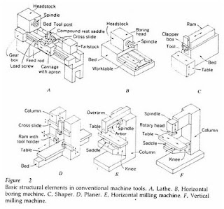
    There is a machine where the object is not moving but it works like a machine moving his tools crab, felts auger (drill press), FRIS machine (milling machine) and grinding. There are also machines in which objects move, but his tools still works like a machine shaved machine, lathe (lathe), and FRIS boring (boring mills). Study the picture below that is the usual processes performed on the engine components.
    In figure 2 below the basic structure seen in conventional machine tools. In figure A. rotating workpiece in a lathe, but the tools (cutting tools) silent. On boring machine (figure B) while the object rotates his tools still work. Or sliding sled delivers tooling to the workpiece is usually more fun than spinning on a rotating shift the workpiece on the tool head remains stationary. Figure C and D are respectively
    crabs and penyerut machine. Form the structure of both machines is influenced by the size of the workpiece where the workpiece little more suited to be machined crab.
    On mowers FRIS, the rotating tool is used only on the drill tool. FRIS machines widely used to cut circular hole, making pathways pegs, creating a gap, sawing, memfris slab and the surface, cut gears and to form the object whose shape is not common.
    Figure 2 E is the machine where the tool rotates FRIS combined with the workpiece moving transversely.


    translate fr Asyari Daryus - Alat Bantu dan Alat Ukur


  • Read more........
  • Classification of Engineering Materials

    Introduction
    The knowledge of materials and their properties is of great significance for a design engineer. The machine elements should be made of such a material which has properties suitable for the conditions of operation. In addition to this, a design engineer must be familiar with the effects which the manufacturing processes and heat treatment have on the properties of the materials. In this chapter, we shall discuss the commonly used engineering materials and their properties in Machine Design.

    The engineering materials are mainly classified as :
    1. Metals and their alloys, such as iron, steel, copper, aluminium, etc.
    2. Non-metals, such as glass, rubber, plastic, etc.
    The metals may be further classified as :
    (a) Ferrous metals, and (b) Non-ferrous metals.
    The *ferrous metals are those which have the iron as their main constituent, such as cast iron, wrought iron and steel.
    The non-ferrous metals are those which have a metal other than iron as their main constituent, such as copper, aluminium, brass, tin, zinc, etc.


    A TEXTBOOK OF Machine Design
    (S.I. UNITS)
    [A Textbook for the Students of B.E. / B.Tech.,
    U.P.S.C. (Engg. Services); Section ‘B’ of A.M.I.E. (I)]
    2005
    EURASIA PUBLISHING HOUSE (PVT.) LTD.
    RAM NAGAR, NEW DELHI-110 055


  • Read more........
  • General Procedure in Machine Design

    In designing a machine component, there is no rigid rule. The problem may be attempted in several ways. However, the general procedure to solve a design problem is as follows :
    1. Recognition of need. First of all, make a complete statement of the problem, indicating the need, aim or purpose for which the machine is to be designed.
    2. Synthesis (Mechanisms). Select the possible mechanism or group of mechanisms which will give the desired motion.
    3. Analysis of forces. Find the forces acting on each member of the machine and the energy transmitted by each member.
    4. Material selection. Select the material best suited for each member of the machine.
    5. Design of elements (Size and Stresses). Find the size of each member of the machine by considering the force acting on the member and the permissible stresses for the material used. It should be kept in mind that each member should not deflect or deform than the permissible limit.
    6. Modification. Modify the size of the member to agree with the past experience and judgment to facilitate manufacture. The modification may also be necessary by consideration of manufacturing to reduce overall cost.
    7. Detailed drawing. Draw the detailed drawing of each component and the assembly of the machine with complete specification for the manufacturing processes suggested.
    8. Production. The component, as per the drawing, is manufactured in the workshop. The flow chart for the general procedure in machine design is shown in Fig. 1.1. Note : When there are number of components in the market having the same qualities of efficiency, durability and cost, then the customer will naturally attract towards the most appealing product. The aesthetic and ergonomics are very important features which gives grace and lustre to product and dominates the market.


    A TEXTBOOK OF Machine Design
    (S.I. UNITS)
    [A Textbook for the Students of B.E. / B.Tech.,
    U.P.S.C. (Engg. Services); Section ‘B’ of A.M.I.E. (I)]
    2005
    EURASIA PUBLISHING HOUSE (PVT.) LTD.
    RAM NAGAR, NEW DELHI-110 055


  • Read more........
  • Evaluation of designs

    However, for the foreseeable future, drawings of various kinds will still be used elsewhere in the design process. Even if the final description is to be in the form of a string of digits, the designer will probably want to make drawings for other purposes.
    One of the most important of these other purposes is the checking, or evaluating, of design proposals before deciding on a final version for manufacture. The whole point of having the process of design separated from the process of making is that
    proposals for new artefacts can be checked before they are put into production. At its simplest, the checking procedure might merely be concerned with, say, ensuring that different components will fit together in the final design; this is an attempt to foresee possible errors and to ensure that the final design is workable. More complicated checking procedures might be concerned with, say, analysing the forces in a proposed design to ensure that each component is designed to withstand the loads on it (Figure 2); this involves a process of refining a design to meet certain criteria such as maximum strength, or minimum weight or cost.
    This process of refinement can be very complicated and can be the most time-consuming part of the design process. Imagine, for example, the design of a bridge. The designer must first propose the form of the bridge and the materials of which it will be made.
    In order to check that the bridge is going to be strong enough and stiff enough for the loads that it will carry, the designer must analyse the structure to determine the ways in which loads will be carried by it, what those loads will be in each member of the structure, what deflections will occur, and so on. After a first analysis,
    the designer might realize, or at least suspect, that changing the locations or angles of some members in the bridge will provide a more efficient distribution of loadings throughout the whole structure. However, these changes will mean that the whole structure will have to be re-analysed and the loads recalculated.
    In this kind of situation it can be easy for the designer to become trapped in an iterative loop of decision-making, where improvements in one part of the design lead to adjustments in another part which lead to problems in yet another part. These problems may mean that the earlier 'improvement' is not feasible. This iteration is a common feature of designing. 
    Nevertheless, despite these potential frustrations, this process of refinement is a key part of designing. It consists, firstly, of analysing a proposed design, and for this the designer needs to apply a range of engineering science or other knowledge. In many cases, specialists with more expert knowledge are called in to carry out
    these analyses. Then, secondly, the results of the analysis are evaluated against the design criteria: does the design come within the cost limit, does it have enough space within it, does it meet the minimum strength requirements, does it use too much fuel, and so on. In some cases, such criteria are set by government regulations, or by industry standards; others are set by the client or customer.
    Many of the analyses are numerical calculations, and therefore again it is possible that drawings might not be necessary. However, specialists who are called in to analyse certain aspects of the design will almost certainly want a drawing, or other model of the design, before they can start work. Visualizations of the proposed design may also be important for the client and designer to evaluate aspects such as appearance, form and colour
    Engineering Design Methods
    Strategies for Product Design
    THIRD EDITION
    Nigel Cross
    The Open University, Mi/ton Keynes, UK
    JOHN WILEY & SONS, LTD
    Chichester- New York. Weinheim • Brisbane. Singapore. Toronto


  • Read more........
  •