Safety factor

A safety factor (SF) or factor of safety (FS) (also called factor of ignorance) is used with plastics or other materials (metals, aluminum, etc.) to provide for the uncertainties associated with any design, particularly when a new product is involved with no direct historical performance record. There are no hard and fast rules to follow in setting a SF. The most basic consideration is the consequences of failure. In addition to the basic uncertainties of graphic design, a designer may also have to consider additional conditions such as: (1) variations in material property data (data in a table is the average and does not represent the minimum required in a design); (2) variation in material performance; (3) effect of size in stating material strength properties; (4) type of loading (static, dynamic, etc.); (5) effect of process (stress concentrations, residual stress, etc.); and (6) overall concern of human safety.
The SF usually used based on experience is 1.5 to 2.5, as is commonly used with metals. Improper use of a SF usually results in a needless waste of material or even product failure. Designers unfamiliar with plastic products can use the suggested preliminary safety factor guidelines in Table 7.3 that provide for extreme safety; intended for preliminary dcsign analysis only. Low range values represent applications where failure is not critical. The higher values apply where failure is critical. Any product designed with these guidelines in mind should conduct tests on the products themselves to relate the guidelines to actual performance. With more experience, more-appropriate values will be developed targeting to use 1.5 to 2.5. After field service of the preliminary designed products has been obtained, action should be taken to consider reducing your SF in order to reduce costs.
Plastics
Engineered
Product
Design
Dominick Rosato and
Donald Rosato
ELSEVIER

  • Read more........
  • Mold Setup & Parison Processing

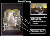
    Performance Objective Setup to generate good container welds with even, easy flash removal at target flash to container interface temperature. Mold Setup •Setup molds with carbon paper to identify even mold compression •Setup mold temperature control of 80F to 110F (25C-40C) at pinch areas to achieve container deflash interface temperature of 180F to 200F (80C to 95C) Processing Techniques •Use mold cracking timer to enable larger containers to vent upon mold opening •Use blow pin lift timer to allow container to release from mold •Insure that container releases easily from the mold –Observe for scrapes on container –Observe for flash retensionto container or mold during mold open and container extraction •Avoid heavy pinch terminations –Program parisonto light weight pinch area –Capture parisonin inflated region –Locate pinch terminations up on base to sidewall radiaway from base footprint –Option: Locate pinch terminations within the base pushup –Option: Locate one end of pinch termination within the base pushup and the other end on the container sidewall Processing Techniques •Pinch weld termination location 1.Locate pinch terminations up on base to sidewall radii away from base footprint 2.Locate pinch terminations within the base pushup 3.Locate one end of pinch termination within the base pushup and the other end on the container sidewall EASTMAN Extrusion Blow Molding Presentation.

    SCALE RATIOS

    Engineering and architectural drawing scales The recommended scales for use in engineering drawing practice and in architectural and building drawings are specified in Table 5.1.


    NOTE: If, for special applications, there is need for a larger enlargement scale or a smaller reduction scale than those shown in the table, the recommended range of scales may be extended in either direction, provided that the required scale is derived from a recommended scale by multiplying by integral powers of 10. In exceptional cases where for functional reasons the recommended scales cannot be applied, intermediate scales may be chosen.

    Australian Standard
    Technical drawing
    Part 101: General principles
    For history before 1992, see Preface.
    Second edition AS 1100.101—1992.
    PUBLISHED BY STANDARDS AUSTRALIA
    (STANDARDS ASSOCIATION OF AUSTRALIA)
    1 THE CRESCENT, HOMEBUSH, NSW 2140
    ISBN 0 7262 7806 8
    Accessed by WOODSIDE ENERGY LTD on 21 Nov 2001


  • Read more........
  • Concurrent Engineering Design

    The production process executes the final results of the design process to produce a product or system. In the pas\. the creative design process was separated from the production process. With the advent of computer modeling. this separation is no longer necessary. and the modern engineering design approach brings both proc'CSses together.
    Concurrent engineering is a nonlinear team approach to design that brings together the input. processes. and output elements necessary to produce a product. The people and processes are brought together at the very beginning. which is not normally done in the linear approach. nte team consists of design and production engineers. technicians. marketing and finance personnel. planners. and managers. who work together [0 solve a problem and produce a product.
    Many companies are finding that concurrent engineering pmcticcs result in a belter. higher-quality product. morc satisfied customers. fewer manufacturing problems. and a shorter cycle time between design initiation ,md final production.
    Figures 2.7 and 2.8 represent the concurrent approach to engineering design. based on 3-D modeling. The three intersecting circles represent the concurrent nature of this design approach. For example. in the ideation phase. design engineers interact with service technicians to ensure that the product willlJe easily serviceable by theconsumer or technician. This type of interaction results in a better prodllct for the consumer. The three intersecting circles also represent the three activities that are a major part of the conCllrrent engineering design process: ideation. refinement. and implementation. These three activities are further divided into smaller segments, as shown by the items surrounding the three circles.
    Design for manufacturabiJity (DFM) and design for assembly (OFA) practices developed out of concurrent
    engineering as an elTon to capture manufacturing and assembly knowledge up front in the imitial design
    process. This allowed engineering and manufacturing professionals 10 speak a common language that results in an optimilcd product design. OFM and OFA cvcntually cxpanded to include other practices. such as design for serviceability and design for reliability. This led to the realization that it is important to include others in the design process. such as marketing, sales. field service, finance, purchasing. and quality control.
    The center area in Figure 2.8 represenL~ the 3-D computer model and rellects the central importance of 3-D
    modeling and graphics knowledge in engineering design and production. With the use of a modeling approach. everyone on the team can have access to the current design through a computer terminal. This data sharing is critically important to the success of the design process.

    The Engineering Design Process
    Bertoline--Wiebe--Miller:
    Fundamentals of Graphics
    Communication,3/e
    The McGraw-Hill
    Companies,2001


  • Read more........
  • Labels

    2d (1) 3D (1) ABG (1) agen JNE (1) almari (1) Alufoil (1) Aluminum Foil (1) anilox roll (1) apartemen (1) Atom (1) autocad (1) backdrop logo (1) bagian dalam (1) bangunan (1) batu alam (1) berkualitas (1) bermutu (1) berpengalaman (1) bertingkat (1) birdview (1) black and white (1) botol plastik (1) cafe (1) classic (1) coklat (1) cold rolled sheet (1) Computer To Plate (1) Consumer Understanding (1) control movement (1) counter (1) CTP (1) denah berwarna (1) denah kantor (1) desain (1) desain cuci mobil (1) desain kamar (1) desain produk (1) design (1) Design and Function (1) design meja (1) Design restaurant (1) design rumah (1) di daerah (1) dinding bata (1) dining (1) Duromer (1) Electrons (1) etnik (1) factors (1) flexo packaging (1) flexo printing (1) food (1) furniture (1) gallus (1) gambar (1) gaya modern (1) gloss (1) grc kotak (1) Halftone (1) hanya 550 ribu (1) harga murah (1) hasil cepat (1) hotel (1) industrial (1) injection (1) Injection Mold (1) ink (1) inovatif (1) install (1) interior (1) interior rumah (1) jasa gambar rumah (1) jasa 3d (1) jasa arsitek (1) jasa desain (1) jasa desain 3d (1) jasa design (1) jasa designer (1) jasa gambar (1) kamar tidur (1) kamar tidur anak (1) kampus (1) karaoke (1) kawasan (1) kawasan industri (1) kemasan (1) kerja di rumah (1) kitchen set (1) kontemporer (1) kosan (1) kost (1) krem (1) laci (1) lamination (1) lithography (1) living room (1) livingroom (1) lounge (1) Luscher MultiDX (1) masterplan (1) matt (1) meja kerja (1) metalworking (1) mewah (1) minimalis (1) minimalist (1) modern (1) mold (1) molding (1) Monomer (1) murah (1) murah. (1) Neutron (1) nuansa remaja (1) offset (1) online design (1) open ceiling (1) outdoor (1) overprint (1) pabrik (1) pantai (1) pencahayaan (1) perumahan (1) pesan desain (1) pesan desain toko (1) plug (1) Polimer (1) Polyaddition (1) Polycondensation (1) Polymerization (1) Polystyrene (1) printing ink (1) Product Creation (1) product function (1) produk katalog (1) Protons (1) Raster Image Processor (1) register (1) rendering (1) resepsionis (1) responsibility (1) resto industrial (1) RIP (1) Rotary (1) ruang kantor (1) ruang keluarga (1) ruang kerja (1) ruang tamu (1) ruang tunggu (1) ruko (1) rumah (1) rumah hook (1) rumah susun (1) rumah tropis (1) scandinavian (1) screen printing (1) sederhana (1) sempoa (1) setup (1) simple sederhana (1) specifications (1) spring (1) steel (1) Struktur Plastik (1) suspension (1) sweet home (1) taman (1) tampak (1) tampak rumah (1) Technological Change (1) terbaru (1) termurah (1) toko aksesoris (1) toko asesoris (1) trapping (1) two cavity (1) unscrewing (1) use (1) uv varnish (1) via online (1) website (1)