Sections and sectional views

A section is used to show the detail of a component, or an assembly, on a particular plane which is known as the cutting plane. A simple bracket is shown in Fig. 8.1 and it is required to draw three sectional views.
Assume that you had a bracket and cut it with a hacksaw along the line marked B–B. If you looked in the direction of the arrows then the end view B–B in the solution (Fig. 8.2), would face the viewer and the surface
indicated by the cross hatching would be the actual metal which the saw had cut through. Alternatively had we cut along the line C–C then the plan in the solution would be the result. A rather special case exists along the plane A–A where in fact the thin web at this point has been sliced. Now if we were to cross hatch all the surface we had cut through on this plane we would give a false impression of solidity. To provide a more realistic drawing the web is defined by a full line and the base and perpendicular parts only have been cross hatched. Note, that cross hatching is never undertaken between dotted lines, hence the full line between the web and the remainder of the detail.
However, the boundary at this point is theoretically a dotted line since the casting is formed in one piece and no join exists here. This standard drawing convention is frequently tested on examination papers.
Cutting planes are indicated on the drawing by a long chain line 0.35 mm thick and thickened at both ends to 0.7 mm. The cutting plane is lettered and the arrows indicate the direction of viewing. The sectional view or plan must then be stated to be A–A, or other letters appropriate to the cutting plane. The cross hatching should always be at 45° to the centre lines, with continuous lines 0.35 mm thick.
If the original drawing is to be microfilmed successive lines should not be closer than 4 mm as hatching lines
tend to merge with much reduced scales. When hatching very small areas the minimum distance between lines
should not be less than 1 mm.
In the case of very large areas, cross hatching may be limited to a zone which follows the contour of the hatched area. On some component detail drawings it may be necessary to add dimensions to a sectional
drawing and the practice is to interrupt the cross hatching so that the letters and numbers are clearly visible.

Manual of
Engineering Drawing
Second edition
Colin H Simmons
I.Eng, FIED, Mem ASME.
Engineering Standards Consultant
Member of BS. & ISO Committees dealing with
Technical Product Documentation specifications
Formerly Standards Engineer, Lucas CAV.
Dennis E Maguire
CEng. MIMechE, Mem ASME, R.Eng.Des, MIED
Design Consultant
Formerly Senior Lecturer, Mechanical and
Production Engineering Department, Southall College
of Technology
City & Guilds International Chief Examiner in
Engineering Drawing
Elsevier Newnes
Linacre House, Jordan Hill, Oxford OX2 8DP
200 Wheeler Road, Burlington MA 01803


  • Read more........
  • The Blow Molding Process

    THEORETICAL BACKGROUND Blow molding is a fabrication process to convert the raw materials (resin) into finished hollow containers (products). It is a manufacturing process by which hollow plastic parts are formed. Principle of the Most Basic Type of Blow Molding 1. Resin is melted by heaters and plasticized by an extruder. 2. Then it is extruded so that it forms a tube-shaped parison matching the size of the product as it passes through the die. 3. Air is then forced into the parison and press it against the inner walls of the mold. After the parison cools and become solid in the mold, the air is released. 4. Finally, the mold will open and the product is deflashed and ejected or taken out the machine. Higher Institute for Plastics Fabrication WORKBOOK for Extrusion Blow Molding Practical Course Prepared by Extrusion Blow Molding Department 1st Edition 2009

    Safety factor

    A safety factor (SF) or factor of safety (FS) (also called factor of ignorance) is used with plastics or other materials (metals, aluminum, etc.) to provide for the uncertainties associated with any design, particularly when a new product is involved with no direct historical performance record. There are no hard and fast rules to follow in setting a SF. The most basic consideration is the consequences of failure. In addition to the basic uncertainties of graphic design, a designer may also have to consider additional conditions such as: (1) variations in material property data (data in a table is the average and does not represent the minimum required in a design); (2) variation in material performance; (3) effect of size in stating material strength properties; (4) type of loading (static, dynamic, etc.); (5) effect of process (stress concentrations, residual stress, etc.); and (6) overall concern of human safety.
    The SF usually used based on experience is 1.5 to 2.5, as is commonly used with metals. Improper use of a SF usually results in a needless waste of material or even product failure. Designers unfamiliar with plastic products can use the suggested preliminary safety factor guidelines in Table 7.3 that provide for extreme safety; intended for preliminary dcsign analysis only. Low range values represent applications where failure is not critical. The higher values apply where failure is critical. Any product designed with these guidelines in mind should conduct tests on the products themselves to relate the guidelines to actual performance. With more experience, more-appropriate values will be developed targeting to use 1.5 to 2.5. After field service of the preliminary designed products has been obtained, action should be taken to consider reducing your SF in order to reduce costs.
    Plastics
    Engineered
    Product
    Design
    Dominick Rosato and
    Donald Rosato
    ELSEVIER


  • Read more........
  • Mold Setup & Parison Processing

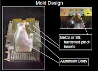
    Performance Objective Setup to generate good container welds with even, easy flash removal at target flash to container interface temperature. Mold Setup •Setup molds with carbon paper to identify even mold compression •Setup mold temperature control of 80F to 110F (25C-40C) at pinch areas to achieve container deflash interface temperature of 180F to 200F (80C to 95C) Processing Techniques •Use mold cracking timer to enable larger containers to vent upon mold opening •Use blow pin lift timer to allow container to release from mold •Insure that container releases easily from the mold –Observe for scrapes on container –Observe for flash retensionto container or mold during mold open and container extraction •Avoid heavy pinch terminations –Program parisonto light weight pinch area –Capture parisonin inflated region –Locate pinch terminations up on base to sidewall radiaway from base footprint –Option: Locate pinch terminations within the base pushup –Option: Locate one end of pinch termination within the base pushup and the other end on the container sidewall Processing Techniques •Pinch weld termination location 1.Locate pinch terminations up on base to sidewall radii away from base footprint 2.Locate pinch terminations within the base pushup 3.Locate one end of pinch termination within the base pushup and the other end on the container sidewall EASTMAN Extrusion Blow Molding Presentation.

    Labels

    2d (1) 3D (1) ABG (1) agen JNE (1) almari (1) Alufoil (1) Aluminum Foil (1) anilox roll (1) apartemen (1) Atom (1) autocad (1) backdrop logo (1) bagian dalam (1) bangunan (1) batu alam (1) berkualitas (1) bermutu (1) berpengalaman (1) bertingkat (1) birdview (1) black and white (1) botol plastik (1) cafe (1) classic (1) coklat (1) cold rolled sheet (1) Computer To Plate (1) Consumer Understanding (1) control movement (1) counter (1) CTP (1) denah berwarna (1) denah kantor (1) desain (1) desain cuci mobil (1) desain kamar (1) desain produk (1) design (1) Design and Function (1) design meja (1) Design restaurant (1) design rumah (1) di daerah (1) dinding bata (1) dining (1) Duromer (1) Electrons (1) etnik (1) factors (1) flexo packaging (1) flexo printing (1) food (1) furniture (1) gallus (1) gambar (1) gaya modern (1) gloss (1) grc kotak (1) Halftone (1) hanya 550 ribu (1) harga murah (1) hasil cepat (1) hotel (1) industrial (1) injection (1) Injection Mold (1) ink (1) inovatif (1) install (1) interior (1) interior rumah (1) jasa gambar rumah (1) jasa 3d (1) jasa arsitek (1) jasa desain (1) jasa desain 3d (1) jasa design (1) jasa designer (1) jasa gambar (1) kamar tidur (1) kamar tidur anak (1) kampus (1) karaoke (1) kawasan (1) kawasan industri (1) kemasan (1) kerja di rumah (1) kitchen set (1) kontemporer (1) kosan (1) kost (1) krem (1) laci (1) lamination (1) lithography (1) living room (1) livingroom (1) lounge (1) Luscher MultiDX (1) masterplan (1) matt (1) meja kerja (1) metalworking (1) mewah (1) minimalis (1) minimalist (1) modern (1) mold (1) molding (1) Monomer (1) murah (1) murah. (1) Neutron (1) nuansa remaja (1) offset (1) online design (1) open ceiling (1) outdoor (1) overprint (1) pabrik (1) pantai (1) pencahayaan (1) perumahan (1) pesan desain (1) pesan desain toko (1) plug (1) Polimer (1) Polyaddition (1) Polycondensation (1) Polymerization (1) Polystyrene (1) printing ink (1) Product Creation (1) product function (1) produk katalog (1) Protons (1) Raster Image Processor (1) register (1) rendering (1) resepsionis (1) responsibility (1) resto industrial (1) RIP (1) Rotary (1) ruang kantor (1) ruang keluarga (1) ruang kerja (1) ruang tamu (1) ruang tunggu (1) ruko (1) rumah (1) rumah hook (1) rumah susun (1) rumah tropis (1) scandinavian (1) screen printing (1) sederhana (1) sempoa (1) setup (1) simple sederhana (1) specifications (1) spring (1) steel (1) Struktur Plastik (1) suspension (1) sweet home (1) taman (1) tampak (1) tampak rumah (1) Technological Change (1) terbaru (1) termurah (1) toko aksesoris (1) toko asesoris (1) trapping (1) two cavity (1) unscrewing (1) use (1) uv varnish (1) via online (1) website (1)