NEW PRODUCT CREATION

The products produced by the company, in their journey, of course undergo stages as according to its life cycle, so that product selection, product definition and product designs need to be continuously updated. Therefore know how to create and develop new products successfully it is an obligation for companies that want to survive.
1. New Product Creation Opportunity
Circumstances that provide opportunities for the emergence of new products include:
1. Consumer Understanding
2. Economic Change
3. Sociological and demographic changes
4. Technological Change
5. Political/Regulatory Changes
6. Other changes such as:
a. Practice in the market
b. Professional standard
c. Supplier
d. Distributor
2. The Importance of New Products
Companies need to continuously make efforts to create new products or product renewal because to be able to balance the competition faced including substitute products as well as changes in consumer needs and desires. Even though in reality many new products fail to get it marketed but persistent efforts to introduce new products must still be done. Therefore, product selection, product definition and product design is very important to be carried out continuously so that the operations manager and
the organization must understand the risk of failure that may occur. And must accommodate many new products while the activities carried out are still carried out.
Product Development Stages
a. Ideas that can come from various sources from within the company, for example the Research section
and Development and from outside through understanding consumer behavior, competition,
technology, workers, supplies. This stage is the basis for entering the market and
usually follow the company's marketing strategy.
b. The ability of the company to realize the idea. By doing coordination of various related departments in the company concerned.
c. Consumer demand to win in competition by identifying position and product benefits that consumers want through attributes about the product.
d. Functional specifications: How can a product function? By going through identification of engineering characteristics of the product, possible comparison with the product from competitors.
e. Product specifications: How is the product made? Through physical specifications such as size,
dimensions.
f. Design review: Are the product specifications the best in meeting the requirements? consumer needs?
g. Market test: Does the product meet consumer expectations? To ensure prospects for future by selling in bulk.
h. Introduction in the market by mass-producing to be marketed.
i. Evaluation: to measure success or failure, because if you fail you can quickly
replaced by other, more profitable products.

Color Reproduction in Printing

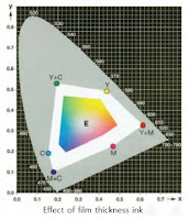
Quality assurance in printing aims to constant/fixed and correct/correct color reproduction/copying via whole in the printing process. For printing ink and color printing supplies, the most important parameter is film thickness ink, halftone value, color balance, ink installation and color series. 
Ink film thickness For technical reasons, the maximum ink film thickness is in offset printing is about 3.5 m. For coated paper and color process related to DIN 16 539 color location which should be achieved/obtained with an ink film thickness between 0.7 and 1.1 m. 
If lithography it doesn't fit / doesn't match, use printing ink that is not appropriate, however, this could happen that point of standardization on the chromatic diagram CIE not reached. Color distance reproduction also decreases if the saturation is not adequate. 
In white area picture shows how narrow the color gap with the ink is less in every three color processes. 
In terms of physics, the effect of the thickness of the ink film on the The view can be explained as follows.
Printing ink does not cover the paper; the ink is, somewhat, transparent. Light enters/penetrates the ink. 
In passing through ink, light facing pigment that absorbs into wavelength whichever is larger or smaller. The higher the pigment concentration and the film thickness The higher the ink/bigger, the more pigment is produced incorporated by the incident light and, as a result, more is absorbed. In the end, the ray of light reaches the surface (white) on the print and reflected supplies. On the way back to the light has to go through the ink film again and only after that he can captured/seen by the eye of the observer. 
The thick printing ink film absorbs more light and reflects less than the thin printing ink film; so that observers see darker, more saturated colors, hues. The part of the light that reaches the eye becomes suitable as basis for estimating/grading each color.

Raster Image Processor RIP Express

Raster Image Processor
translate postscript language for imagessetter
imagesetter: a machine that produces high-resolution output on film
translate image into raster
translate bitmap to halftone
work flow technology to increase processing speed and ease of processing data electronically
print directly
RIP(express)
RipExpress is based on Adobe's Configurable PostScript Interpreter (CPSI) to interpret PostScript files accurately and consistently.
RipExpress by Monotype Systems is software
This versatile RIP can handle color and monochrome files from PostScript 3
RipExpress that combines optimum performance with an exclusive and easy-to-use interface
available for Sun UltraSPARC and Window NT platforms on Pentium PCs.
RipExpress is a full implementation of the PostScript 3 software from Adobe
which offers increased performance and benefits such as direct processing and printing of PDF files.
Super Screens are used to show superior looking finishes. ,
With Super Screens, 'appeal' can be removed from imagesetting and direct-to-plate systems
and can produce 4096 levels of gray on these high-resolution tools.
Color preview provides a full color preview of the RIP work on the screen
Previewed bitmap images can be sent directly to a high-resolution recorder or
alternatively printed to a color proofer for deeper evaluation.
Easy-to-use RipExpress features with a graphical interface
Uses Adobe's CPSI to ensure perfect compatibility with the pure PostScript 3 language.
Output to Laserbus for connecting all kinds of recorders using Personality Interfaces
Input spooling and hold facilities, and output spooling and hold
Color page preview on screen. 
Halftone and calibration table.
A set of 136 fonts provided by default.
Multiple inputs using Ethertalk, TCP/IP, LPR, drop folder and MGS3 special input.
Save media usage with Trim Page which removes excess white area under the page
Film Saving which automatically rotates the page so that it can save material.
Anamorphic scaling with separate X & Y scale control
In-place compression and decompression for bitmap files
Additional RIP to TIFF Options: Output can be set to output 1 bit TIFF files as uncompressed, Packbits, CCITT Huffman, Fax Group 3 and Fax Group 4.
OPI can provide a pointer where MGS3 can put high-resolution images when they log into the system
Then OPI substitution can occur on the RIP when the page is printed
FM Screens: Stochastic screening using Adobe Brilliant Screens
PrintExpress Snap Shots PrintExpress/CPM
is a digital workflow system that includes a number of software
which is used to link page builder and press printing applications.
PrintExpress handles the steps from receiving a page in PostScript or PDF format through
RIPAN, pagepairing, spooling, proofing, tracking and remote transmission to printing in different places
The set of modules that PrintExpress includes are:
PostScript / PDF Spooler This module accepts PostScript or PDF format files from other systems
like a page generator on a PC or Mac or an OPI server.
This module uses standard input protocols such as PAP (Apple), TCP/IP, drop file or from OPI MG3 server.

Design Definition and Design Technology

Design Definition 
The term “design” has many connotations. They can range from industrial designers to high structural load engineering designers. A few of these will be summarized in order to highlight that different designer skills are used to meet different product requirements. Essentially it is the process of devising a product that fulfills as completely as possible the total requirements of the user, and at the same time satisfies needs in terms of cost-effectiveness or ROI (return on investment). It encompasses the important interrelationship practical factors such as shape, material selection (including unreinforced and reinforced, elastomers, foams, etc.), consolidation of subparts, fabricating selection, and others that provide low cost-to-performance products. Product design is as much an art as a science. Recognize that a successful design is usually a compromise between the requirements of product function, productibility, and cost. Basically design is the mechanism whereby a requirement is converted to a meaningful plan. Design guidelines for plastics have existed for over a century. With plastics to a greater extent than other materials, an opportunity exists to optimize product design by focusing on material composition and orientation to structural member geometry when required. The type of designer to produce a product depends on the product requirements. As an example in most cases an engineering designer is not needed because the product has no major load requirement. All that is needed is experience and/or a logical evaluation approach based on available material and processing data. This practical approach is the least consumer of time and least expensive. 
Design Technology 
It is the prediction of performance in its broadest sense, including all the characteristics and properties of materials that are essential and relate to the processing of the plastic. To the designer, an example of a strict definition of a design property could be one that permits calculating product dimensions from a stress analysis. Such properties obviously are the most desirable upon which to base material selections. However, like with metals, there are many stresses that cannot be accurately analyzed. Hence one is forced to rely on properties that correlate with performance requirements. Where the product has critical performance requirements, such as ensuring safety to people, production prototypes will have to be exposed to the requirements it is to meet in service. In plastics, these correlative properties, together with those that can be used in design equations, generally are called engineering properties. They encompass a variety of situations over and above the basic static strength and rigidity requirements, such as impact, fatigue, flammability, chemical resistance, and temperature.

Injection Mold for the Body of a Tape Cassette

product design development
Injection Mold for the Body of a Tape-Cassette Holder Made from High-Impact Polystyrene.
Molded Part: Design and Function 
A cubic molded part of impact-resistant polystyrene forms the main body of a tape-cassette holder consisting of a number of injectionmolded parts. Several cassette holders can be stacked on top of each other by snap fits to yield a tower that can accommodate more cassettes. The molded part, which has a base measuring 162mm x 162mm and is 110mm tall, consists of a central square-section rod whose two ends are bounded by two square plates. Between these plates, and parallel to the central rod, are the walls, forming four bays for holding the cassettes. Single-Cavity Mold with Four Splits The mold, with mold fixing dimensions of 525mm x 530mm and 500mm mold height, is designed as a single-cavity mold with four mechanical splits (Fig. 3). The movable splits (9) are mounted on the ejector side of the mold with guide plates (21) and on guide bars (20). The splits form the external side walls of the molded part while the internal contours of the bay’s comprising ribs, spring latches and apertures are made by punches (34) that are fitted into the splits and bolted to them. Core (6), which is mounted along with punch (7) on platen (23), forms the bore for the square-section rod. The punch (7) and the runner plate (14) form the top and bottom sides of the molded part. When the mold is closed, the four splits are supported by the punch (7) and each other via clamping surfaces that are inclined at less than 45. Furthermore, the apertures in the molded part ensure good support between punches (34) on the splits, core (6) and runner plate (14). The closed splits brace themselves outwardly against four wedge plates (12) which are mounted on the insert plate (18) with the aid of wear plates (13). Adjusting plates (11) ensure accurate fitting of the splits. Each slide is driven by two angle pins (8), located in insert plate (18) on the feed side. Pillars (39) and bushings (37) serve to guide the mold halves. The plates of each mold half are fixed to each other with locating pins (27). The molded part is released from the core by ejector pins (25), which are mounted in the ejector plates (3, 4). Plate (23) is supported on the ejector side against the clamping plate via two rails (40) and, in the region of the ejector plates beneath the cavity, by rolls (2). Feeding via Runners The molding compound reaches the feed points in the corners of the square-section rod via sprue bushing (16) and four runners. The rod’s corners have a slightly larger flow channel than the other walls of the molded part. The sprue bushing is secured against turning by pin (15). Mold Temperature Control Cooling channels are located in the core retainer plate (22) and the insert plate (18). Punch (7) is cooled as shown in Fig. 4. Core (6) is fitted with two cooling pipes, while punch (34) is fitted with cooling pipe (35). Furthermore, the slide (9) are cooled. Demolding: Latches Spring Back As the mold opens, the slides (9) are moved by the angle pins (8) to the outside until the punches (34) are retracted from the side bays of the molded part. As Fig. 5 shows, the cavities of the spring latches Z are located on the one hand between the faces of the four punches (34) and runner plate (14) and, on the other, between the two adjacent side faces of the punches (34). On opening of the mold, the ratio of the distance moved by the slides to the opening stroke between runner plate (14) and slides is the tangent of the angle formed by the angle pins and the longitudinal axis of the mold. Thus, when the mold opens, enough space is created behind the latches Z to enable them to spring back when the punches (34) slide over the wedge-shaped elevations (a) of the latches (Fig. 5). The situation is similar for ejecting latches between adjacent punch faces. As the mold opens further, the angle pins and the guide bores in the slides can no longer come into play. The open position of the slides is secured by the ball catches (33). The molded part remains on core (6) until stop plate (29) comes into contact with the ejector stop of the machine and displaces ejector plates (3, 4) with ejector pins (24, 25). The molded part is ejected from the core, and the sprue from the runners. When the stop plates are actuated, helical springs are compressed (30) that, as the mold is closing, retract the ejector pins before the slides close. Return pins (26) and buffer pins (19) ensure that the ejector system is pushed back when the mold closes completely.

Learn Flexo Packaging Register Overprint Trapping

linearis machine printing
Learning flexo is fun, maybe for some people in Indonesia. Of course, the flexo printing technique, especially the CI type, sounds foreign. I'm only 6 years old getting to know flexo printing until this article was written, this poses a big challenge for me to know more about it. In this article I want to introduce flexo printing for those who want to learn flexo printing techniques. 
Initially Flexo printing used rubber (like a Stamp) which was then pressed to print the image. The first flexo printing machine was made in 1980 in England by Bibby Baron and Sons, at the same time the same machine was also made in Germany which is named Aniline because it uses Aniline ink.
In 1950 Franklin Moses proposed that the Aniline printing process be renamed be Flexo print.
For the next 30 years the flexo machine is still considered a printing technique for quality low so that it is generally used to print corrugated boxes. But with the discovery of UV ink and its drying, then flexo print using ink UV began to be used to print labels.
Basically the preparation for design and artwork for flexo printing is the same as artwork design work for other printing systems, but there are some differences fundamentals that we must understand. To print flexo what we see on the computer screen and what we see in the proof, may not be the same as the final flexo print.
Proof is made only to see the layout (position of the layout).
A. TERMS IN FLEXO
1. TYPOGRAPHY
Considerations for font size, object ex and line thickness
2. LINE REVERSE / KNOCKOUT
Line object, it is recommended to be limited to no more than 1 color for color
the arrangement.
3. DROP SHADOW
4. REGISTER
5. OVERPRINT
6. CONVERTING TYPE TO OUTLINE
7. TRAPPING
8. DIE LINE
B. HALFTONE SCREENS
Halftone is a collection of small dots that when viewed from a distance will appear
like a stream of gray or colored smelly shadows. The number of the dots must be
enough to be boxy. For color images, there is a stack of dots
consisting of dot colors cyan, magentha, yellow and black (CMYK). The higher the screen
frequency (the more lines per inch), the smoother the image will be. For flexo
quality can be used up to 175 lpi. The defaults are 100, 120, 133, 150 and 175 lpi.
Dot is a dot (circle) that is used to form halftone printing.
The shape of the dot also varies, including round, square, elliptical and octagonal.
In general, a round pacifier is widely used.
The things that cause dot enlargement:
. Excessive ink absorption
. The ink spreads to the material because the viscosity of the ink is too high, making it difficult
spread
. Over-pressed photopolymer (flexo must be with “kiss printing”
. Machine is not good
C. Ink
Flexo ink comparison:
1. Flexo Waterbased Ink
Excess :
- Does not require Exhaust
- Does not cause air pollution
- Excellent absorption, low energy cost for absorbent materials
- No need for explosion proof equipment
- Does not pose a problem for transportation (harmless)
Deficiency :
- If printed on plastic film, it can cause problems with sticking
as well as drying. But for modern machines this problem has been solved.
- Less shiny
- Sometimes foamy
- Cleaning is quite difficult
2. Solvent based flexo ink
Excess :
- Easy to use (set up, cleaning)
- Dries quickly
- Good adhesion to plastic film
- High mechanical resistance
- Stable surface tension
- Anilox is easy to clean (compared to using waterbased inks)
Deficiency :
- Evaporation of solvents causes pollution (harmful to health)
- Air exhaust equipment is required and must be explosion-proof
- There are regulations for the use and storage of solvents and inks
3. UV flexo ink
Excess :
- Does not require Exhaust
- The ink does not dry on the machine
- No need for explosion proof equipment
- Very glossy (glossy)
Deficiency :
- The price of ink is expensive
- Requires a high enough energy, especially if using a cooling roll
- If the temperature changes, the viscosity will also change and can
cause discoloration especially special colors.
- Some materials do not stick well.
by Su-harto

Labels

2d (1) 3D (1) ABG (1) agen JNE (1) almari (1) Alufoil (1) Aluminum Foil (1) anilox roll (1) apartemen (1) Atom (1) autocad (1) backdrop logo (1) bagian dalam (1) bangunan (1) batu alam (1) berkualitas (1) bermutu (1) berpengalaman (1) bertingkat (1) birdview (1) black and white (1) botol plastik (1) cafe (1) classic (1) coklat (1) cold rolled sheet (1) Computer To Plate (1) Consumer Understanding (1) control movement (1) counter (1) CTP (1) denah berwarna (1) denah kantor (1) desain (1) desain cuci mobil (1) desain kamar (1) desain produk (1) design (1) Design and Function (1) design meja (1) Design restaurant (1) design rumah (1) di daerah (1) dinding bata (1) dining (1) Duromer (1) Electrons (1) etnik (1) factors (1) flexo packaging (1) flexo printing (1) food (1) furniture (1) gallus (1) gambar (1) gaya modern (1) gloss (1) grc kotak (1) Halftone (1) hanya 550 ribu (1) harga murah (1) hasil cepat (1) hotel (1) industrial (1) injection (1) Injection Mold (1) ink (1) inovatif (1) install (1) interior (1) interior rumah (1) jasa gambar rumah (1) jasa 3d (1) jasa arsitek (1) jasa desain (1) jasa desain 3d (1) jasa design (1) jasa designer (1) jasa gambar (1) kamar tidur (1) kamar tidur anak (1) kampus (1) karaoke (1) kawasan (1) kawasan industri (1) kemasan (1) kerja di rumah (1) kitchen set (1) kontemporer (1) kosan (1) kost (1) krem (1) laci (1) lamination (1) lithography (1) living room (1) livingroom (1) lounge (1) Luscher MultiDX (1) masterplan (1) matt (1) meja kerja (1) metalworking (1) mewah (1) minimalis (1) minimalist (1) modern (1) mold (1) molding (1) Monomer (1) murah (1) murah. (1) Neutron (1) nuansa remaja (1) offset (1) online design (1) open ceiling (1) outdoor (1) overprint (1) pabrik (1) pantai (1) pencahayaan (1) perumahan (1) pesan desain (1) pesan desain toko (1) plug (1) Polimer (1) Polyaddition (1) Polycondensation (1) Polymerization (1) Polystyrene (1) printing ink (1) Product Creation (1) product function (1) produk katalog (1) Protons (1) Raster Image Processor (1) register (1) rendering (1) resepsionis (1) responsibility (1) resto industrial (1) RIP (1) Rotary (1) ruang kantor (1) ruang keluarga (1) ruang kerja (1) ruang tamu (1) ruang tunggu (1) ruko (1) rumah (1) rumah hook (1) rumah susun (1) rumah tropis (1) scandinavian (1) screen printing (1) sederhana (1) sempoa (1) setup (1) simple sederhana (1) specifications (1) spring (1) steel (1) Struktur Plastik (1) suspension (1) sweet home (1) taman (1) tampak (1) tampak rumah (1) Technological Change (1) terbaru (1) termurah (1) toko aksesoris (1) toko asesoris (1) trapping (1) two cavity (1) unscrewing (1) use (1) uv varnish (1) via online (1) website (1)