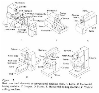
Structure For Cutting Machine

There is a machine where the object is not moving but it works like a machine moving his tools crab, felts auger (drill press), FRIS machine (milling machine) and grinding. There are also machines in which objects move, but his tools still works like a machine shaved machine, lathe (lathe), and FRIS boring (boring mills). Study the picture below that is the usual processes performed on the engine components.
In figure 2 below the basic structure seen in conventional machine tools. In figure A. rotating workpiece in a lathe, but the tools (cutting tools) silent. On boring machine (figure B) while the object rotates his tools still work. Or sliding sled delivers tooling to the workpiece is usually more fun than spinning on a rotating shift the workpiece on the tool head remains stationary. Figure C and D are respectively
crabs and penyerut machine. Form the structure of both machines is influenced by the size of the workpiece where the workpiece little more suited to be machined crab.
On mowers FRIS, the rotating tool is used only on the drill tool. FRIS machines widely used to cut circular hole, making pathways pegs, creating a gap, sawing, memfris slab and the surface, cut gears and to form the object whose shape is not common.
Figure 2 E is the machine where the tool rotates FRIS combined with the workpiece moving transversely.


translate fr Asyari Daryus - Alat Bantu dan Alat Ukur


  • Read more........
  • Classification of Engineering Materials

    Introduction
    The knowledge of materials and their properties is of great significance for a design engineer. The machine elements should be made of such a material which has properties suitable for the conditions of operation. In addition to this, a design engineer must be familiar with the effects which the manufacturing processes and heat treatment have on the properties of the materials. In this chapter, we shall discuss the commonly used engineering materials and their properties in Machine Design.

    The engineering materials are mainly classified as :
    1. Metals and their alloys, such as iron, steel, copper, aluminium, etc.
    2. Non-metals, such as glass, rubber, plastic, etc.
    The metals may be further classified as :
    (a) Ferrous metals, and (b) Non-ferrous metals.
    The *ferrous metals are those which have the iron as their main constituent, such as cast iron, wrought iron and steel.
    The non-ferrous metals are those which have a metal other than iron as their main constituent, such as copper, aluminium, brass, tin, zinc, etc.


    A TEXTBOOK OF Machine Design
    (S.I. UNITS)
    [A Textbook for the Students of B.E. / B.Tech.,
    U.P.S.C. (Engg. Services); Section ‘B’ of A.M.I.E. (I)]
    2005
    EURASIA PUBLISHING HOUSE (PVT.) LTD.
    RAM NAGAR, NEW DELHI-110 055


  • Read more........
  • General Procedure in Machine Design

    In designing a machine component, there is no rigid rule. The problem may be attempted in several ways. However, the general procedure to solve a design problem is as follows :
    1. Recognition of need. First of all, make a complete statement of the problem, indicating the need, aim or purpose for which the machine is to be designed.
    2. Synthesis (Mechanisms). Select the possible mechanism or group of mechanisms which will give the desired motion.
    3. Analysis of forces. Find the forces acting on each member of the machine and the energy transmitted by each member.
    4. Material selection. Select the material best suited for each member of the machine.
    5. Design of elements (Size and Stresses). Find the size of each member of the machine by considering the force acting on the member and the permissible stresses for the material used. It should be kept in mind that each member should not deflect or deform than the permissible limit.
    6. Modification. Modify the size of the member to agree with the past experience and judgment to facilitate manufacture. The modification may also be necessary by consideration of manufacturing to reduce overall cost.
    7. Detailed drawing. Draw the detailed drawing of each component and the assembly of the machine with complete specification for the manufacturing processes suggested.
    8. Production. The component, as per the drawing, is manufactured in the workshop. The flow chart for the general procedure in machine design is shown in Fig. 1.1. Note : When there are number of components in the market having the same qualities of efficiency, durability and cost, then the customer will naturally attract towards the most appealing product. The aesthetic and ergonomics are very important features which gives grace and lustre to product and dominates the market.


    A TEXTBOOK OF Machine Design
    (S.I. UNITS)
    [A Textbook for the Students of B.E. / B.Tech.,
    U.P.S.C. (Engg. Services); Section ‘B’ of A.M.I.E. (I)]
    2005
    EURASIA PUBLISHING HOUSE (PVT.) LTD.
    RAM NAGAR, NEW DELHI-110 055


  • Read more........
  • Evaluation of designs

    However, for the foreseeable future, drawings of various kinds will still be used elsewhere in the design process. Even if the final description is to be in the form of a string of digits, the designer will probably want to make drawings for other purposes.
    One of the most important of these other purposes is the checking, or evaluating, of design proposals before deciding on a final version for manufacture. The whole point of having the process of design separated from the process of making is that
    proposals for new artefacts can be checked before they are put into production. At its simplest, the checking procedure might merely be concerned with, say, ensuring that different components will fit together in the final design; this is an attempt to foresee possible errors and to ensure that the final design is workable. More complicated checking procedures might be concerned with, say, analysing the forces in a proposed design to ensure that each component is designed to withstand the loads on it (Figure 2); this involves a process of refining a design to meet certain criteria such as maximum strength, or minimum weight or cost.
    This process of refinement can be very complicated and can be the most time-consuming part of the design process. Imagine, for example, the design of a bridge. The designer must first propose the form of the bridge and the materials of which it will be made.
    In order to check that the bridge is going to be strong enough and stiff enough for the loads that it will carry, the designer must analyse the structure to determine the ways in which loads will be carried by it, what those loads will be in each member of the structure, what deflections will occur, and so on. After a first analysis,
    the designer might realize, or at least suspect, that changing the locations or angles of some members in the bridge will provide a more efficient distribution of loadings throughout the whole structure. However, these changes will mean that the whole structure will have to be re-analysed and the loads recalculated.
    In this kind of situation it can be easy for the designer to become trapped in an iterative loop of decision-making, where improvements in one part of the design lead to adjustments in another part which lead to problems in yet another part. These problems may mean that the earlier 'improvement' is not feasible. This iteration is a common feature of designing. 
    Nevertheless, despite these potential frustrations, this process of refinement is a key part of designing. It consists, firstly, of analysing a proposed design, and for this the designer needs to apply a range of engineering science or other knowledge. In many cases, specialists with more expert knowledge are called in to carry out
    these analyses. Then, secondly, the results of the analysis are evaluated against the design criteria: does the design come within the cost limit, does it have enough space within it, does it meet the minimum strength requirements, does it use too much fuel, and so on. In some cases, such criteria are set by government regulations, or by industry standards; others are set by the client or customer.
    Many of the analyses are numerical calculations, and therefore again it is possible that drawings might not be necessary. However, specialists who are called in to analyse certain aspects of the design will almost certainly want a drawing, or other model of the design, before they can start work. Visualizations of the proposed design may also be important for the client and designer to evaluate aspects such as appearance, form and colour
    Engineering Design Methods
    Strategies for Product Design
    THIRD EDITION
    Nigel Cross
    The Open University, Mi/ton Keynes, UK
    JOHN WILEY & SONS, LTD
    Chichester- New York. Weinheim • Brisbane. Singapore. Toronto


  • Read more........
  •