Roughness and waviness

A trace across a surface provides a profile of that surface which will  contain short and long wavelengths (see Figure 4.11). In order for a surface to be correctly inspected, the short and long wavelength  components need to be separated so they can be individually analysed. The long waves are to do with dimensions and the short waves are to do with the SE Both can be relevant to function but in different ways. Consider the block in Figure 6.1. This has been produced on a shaping machine. The block surface undulates in a variety of ways. There is a basic roughness, created by the tool feed marks, which is superimposed on the general plane of the surface.
Thus, one can identify two different wavelengths, one of a small scale and one of a large scale. These are referred to as the roughness and waviness components.
Roughness and waviness have different influences on functional performance. A good example illustrating the differences concerns automotive bodies. Considering the small-scale amplitudes and wavelengths called 'roughness', it is the roughness, not waviness, which influences friction, lubrication, wear and galling, etc. The
next scale up from roughness is 'waviness' and it is known that the visual appearance of painted car bodies correlates more with waviness than roughness. The reason for this is the paint depth is about 100um and it has a significant filtering effect on roughness but not waviness.


Engineering Drawing for Manufacture
by Brian Griffiths
Publisher: Elsevier Science & Technology Books


  • Read more........
  • DESIGNATION AND RELATIVE POSITIONS OF VIEWS

    An object positioned in space may be imagined as surrounded by six mutually perpendicular planes. So, for any object, six different views may be obtained by viewing at it along the six directions, normal to these planes. Figure 3.5 shows an object with six possible directions to obtain the different views which are designated as follows: 1. View in the direction a = view from the front 2. View in the direction b = view from above 3. View in the direction c = view from the left 4. View in the direction d = view from the right 5. View in the direction e = view from below 6. View in the direction f = view from the rear Figure 3.6a shows the relative positions of the above six views in the first angle projection and Fig.3.6b, the distinguishing symbol of this method of projection. Figure 3.7 a shows the relative position of the views in the third angle projection and Fig. 3.7b, the distinguishing symbol of this method of projection. NOTE A comparison of Figs. 3.6 and 3.7 reveals that in both the methods of projection, the views are identical in shape and detail. Only their location with respect to the view from the front is different. MACHINE DRAWING Third Edition Dr.K.I. Narayana Dr.P. Kannalah K. Venkata Reddy NEW AGE INTERNATIONAL (P) LIMITED, PUBLISHERS

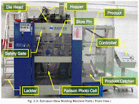
    Extrusion Blow Molding Machine Parts and Functions

    Extrusion Blow Molding Machine Parts and Functions
    • Extruder Motor—Drives the screw in the barrel to rotate and push the
    melted material into the die head.
    • Gearbox—Reduces the speed of the extruder motor into a required speed enough to push the material into the die head.
    • Hopper—A feed reservoir into which the material is loaded.
    • Extruder—A part of the machine that accepts solid resin material, conveys it in a surrounding barrel by means of a rotating screw, melts the
    material by means of heaters, and pumps it under pressure into the die
    head.
    • Cooling Fans—Cools down the barrel during machine shut down to prevent the material from degradation.
    • Heating Bands—Device attached on the barrel and the die head used to melt the solid material at a required set temperature.
    • Die Head—Used to form the melted resin into a parison and also used for adjusting the characteristics of molten resin to create a stable parison.
    • Die & Pin—Used to align the flow of parison to get a good and centered parison.
    • Hot Cutter—Cuts the parison after the mold is closed for the blowing process.
    • Blow Pin—Used to blow compressed air into the parison to inflate it after the mold has been closed and form the desired design of the mold.
    • Mold—A hollow form or a cavity into which a molten plastic material, called parison, is introduced to give the shape of the required component.
    • Deflasher—Used to cut the excess material on the bottle which is called a flash material (top and bottom).
    • Post Cooling—A part of the machine that is used to cool down the inside of the bottle, to lessen the cooling time required inside the mold.
    • Article Discharge—A part of the machine used to take the bottle out.

    Higher Institute for Plastics Fabrication
    WORKBOOK
    for
    Extrusion Blow Molding
    Practical Course
    Prepared by
    Extrusion Blow Molding Department
    1st Edition 2009


  • Read more........
  • What Is Computer-Aided Process Planning (CAPP)?

    In this section we introduce the topic of CAPP, and review important components of this technology. Chang and Wysk (1985) define process planning as “machining processes and parameters that are to be used to convert (machine) a workpiece from its initial form to a final form predetermined from an engineering drawing.” Implicit in their definition is the selection of machining resources (machine and cutting tools), the specification of setups and fixturing, and the generation of operation
    sequences and numerical control (NC) code. Traditionally, the task of process planning is performed by a human process planner with acquired expertise in machining practices who determines from a part’s engineering drawings what the machining requirements are.

    Manual process planning has many drawbacks. In particular, it is a slow, repetitive task that is  prone to error. With industry’s emphasis on automation for improved productivity and quality, computerized CAD and computer-aided manufacturing (CAM) systems which generate the data for driving computer numerical control (CNC) machine tools, are the state-of-the-art. Manual process planning in this context is a bottleneck to the information flow between design and manufacturing.

    CAPP is the use of computerized software and hardware systems for automating the process planning task. The objective is to increase productivity and quality by improving the speed and accuracy of process planning through automation of as many manual tasks as possible. CAPP will increase automation and promote integration among the following tasks:
    1. Recognition of machining features and the construction of their associated machining volumes from a geometric CAD model of the part and workpiece
    2. Mapping machining volumes to machining operations
    3. Assigning operations to cutting tools
    4. Determining setups and fixturing
    5. Selecting suitable machine tools
    6. Generating cost-effective machining sequences
    7. Determining the machining parameters for each operation
    8. Generating cutter location data and finally NC machine code
    Traditionally, CAPP has been approached in two ways. These two approaches are variant process planning and generative process planning. In the following section we discuss these and other issues in a review of work in this field.

    THE
    MECHANICAL
    SYSTEMS
    DESIGN
    HANDBOOK
    Modeling, Measurement,
    and Control
    OSITA D. I. NWOKAH
    YILDIRIM HURMUZLU
    Southern Methodist University
    Dallas, Texas
    CRC PRESS
    Boca Raton London New York Washington, D.C.


  • Read more........
  •