Modulus of Elasticity

There are different techniques that have been used for over a century to increase the modulus of elasticity of plastics. Orientation or the use of fillers and/or reinforcements such as RPs can modifl the plastic. There is also the popular and extensively used approach of using geometrical design shapes that makes the best use of materials to improve stiffness even for those that have a low modulus. Structural shapes that are applicable to all materials include shells, sandwich structures, dimple sheet surfaces, and folded plate structure.
Plastics
Engineered
Product
Design
Dominick Rosato and
Donald Rosato
Elsevier Ltd, The Boulevard, Langford Lane, Kidlington, Oxford OX5 lGB, UK
Elsevier Inc, 360 Park Avenue South, New York, NY 10010-1710, USA
Elsevier Japan, Tsunashima Building Annex, 3-20-12 Yushima, Bunkyo-ku, Tokyo 113,
Japan

Mechanical Properties of Metals (2)

6. Brittleness.
It is the property of a material opposite to ductility. It is the property of breaking of a material with little permanent distortion. Brittle materials when subjected to tensile loads, snap off without giving any sensible elongation. Cast iron is a brittle material.

7. Malleability.
It is a special case of ductility which permits materials to be rolled or hammered into thin sheets. A malleable material should be plastic but it is not essential to be so strong. The
malleable materials commonly used in engineering practice (in order of diminishing malleability) are lead, soft steel, wrought iron, copper and aluminium.

8. Toughness.
It is the property of a material to resist fracture due to high impact loads like hammer blows. The toughness of the material decreases when it is heated. It is measured by the amount of energy that a unit volume of the
material has absorbed after being stressed upto the point of fracture. This property is desirable in parts subjected to shock and impact loads.

9. Machinability. It is the property of a material which refers to a relative case with which a material can be cut. The machinability of a material can be measured in a number of ways such as comparing the tool life for cutting different materials or thrust required to remove the material at some given rate or the energy required to remove a unit volume of the material. It may be noted that brass can be easily machined than steel.

10. Resilience. It is the property of a material to absorb energy and to resist shock and impact loads. It is measured by the amount of energy absorbed per unit volume within elastic limit. This property is essential for
spring materials.

FIRST MULTICOLOUR EDITION
A TEXTBOOK OF
Machine
Design
(S.I. UNITS)
[A Textbook for the Students of B.E. / B.Tech.,
U.P.S.C. (Engg. Services); Section ‘B’ of A.M.I.E. (I)]
R.S. KHURMI
J.K. GUPTA
EURASIA PUBLISHING HOUSE (PVT.) LTD.
RAM NAGAR, NEW DELHI-110 055


  • Read more........
  • PRESS FITS

    When one object such as a shaft is assembled to another by forcing it into a hole that is slightly too small, the operation is known as press fitting. Press fits can be designed between similar plastics, dissimilar plastics, or more commonly between a plastic and a metal. A typical example occurs when a plastics hub in the form of a control knob or gear is pressed on a metal shaft. The position is reversed when a plastics sleeve or bearing is pressed into a metal bore.
    Press fits are simple and inexpensive but there are some problems to look out for. The degree of interference between the shaft and the hole is critical. If it is too small, the joint is insecure. If it is too great, the joint is difficult to assemble and the material will be over-stressed. Unlike a snap fit, the press fit remains permanently stressed and it is the elastic deformation of the plastics part that supplies the force to hold the joint together.
    When plastics materials are exposed to permanent stress the result is creep. This means that as time goes by, the force exerted by the press fit becomes less, lthough not necessarily to a significant extent.
    There are two other pitfalls for press fits. Manufacturing tolerances on the shaft and hole must be taken into account to see whether the two extreme cases remain viable.
    And when the joint is made between dissimilar materials, an increase in temperature will change the degree of interference between the parts. Remember too, that at elevated temperatures the effect of creep will be greater.
    One way of countering the effect of creep in a shaft and hub press fit is to provide a straight medium knurl on the metal shaft.
    The plastics hub material will tend to cold flow into the grooves of the knurl, giving a degree of mechanical interference between the parts. The frictional effect is also greater because the surface area of the joint has been increased by the knurl.

    DESIGN GUIDES
    for
    PLASTICS
    Clive Maier, Econology Ltd
    Plastics Design Group - Plastics Consultancy Network
    British Plastics Federation
    pdg
    plastics design group
    December 2004 Edition


  • Read more........
  • SIZE OF DRAWING SHEETS

    2.4.1 Preferred sizes The preferred size of drawing sheets shall be the ISO-A series for which the designation and dimensions are as given in Table 2.1. Preferred size drawing sheets, with slightly wider borders to take account of preprinting considerations, shall have dimensions as given in Table 2.2. Such sheets shall be additionally designated by the prefix R, i.e. RA0, RA1, RA2, RA3, and RA4. Where drawing sheets of a greater length are required, they should be selected from and have dimensions in accordance with one of the series given in Table 2.3. Such sheets shall bedesignated A3 × 3, A3 × 4, A4 × 3, A4 × 4, and A4 × 5. 2.4.2 Non-preferred sizes The non-preferred size of drawing sheets shall be the ISO-B series for which the designations and dimensions are as given in Table 2.4. Non-preferred size drawing sheets, with slightly wider borders to take account of preprinting considerations, shall have dimensions as given in Table 2.5. Such sheets shall be additionallydesignated by the prefix R, i.e. RB1, RB2, RB3, and RB4. 2.4.3 Roll drawings Standard widths of roll drawings shall be 860 mm and 610 mm. Lengthsof the roll drawing sheets shall be determined to suit the requirements of the individual drawings. Australian Standard Technical drawing Part 101: General principles For history before 1992, see Preface. Second edition AS 1100.101—1992. Incorporating Amdt 1-1994 PUBLISHED BY STANDARDS AUSTRALIA (STANDARDS ASSOCIATION OF AUSTRALIA) 1 THE CRESCENT, HOMEBUSH, NSW 2140

    Mechanical Properties of Metals

    The mechanical properties of the metals are those which are associated with the ability of the material to resist mechanical forces and load. These mechanical properties of the metal include strength, stiffness, elasticity, plasticity, ductility, brittleness, malleability, toughness, resilience, creep and hardness. We shall now discuss these properties as follows:
    1. Strength. It is the ability of a material to resist the externally applied forces without breaking or yielding. The internal resistance offered by a part to an externally applied force is called *stress.
    2. Stiffness. It is the ability of a material to resist deformation under stress. The modulus of elasticity is the measure of stiffness.
    3. Elasticity. It is the property of a material to regain its original shape after deformation when the external forces are removed. This property is desirable for materials used in tools and machines. It may be noted that steel is more elastic than rubber.
    4. Plasticity. It is property of a material which retains the deformation produced under load permanently. This property of the material is necessary for forgings, in stamping images on coins and in ornamental work.
    5. Ductility. It is the property of a material enabling it to be drawn into wire with the application of a tensile force. A ductile material must be both strong and plastic. The ductility is usually measured by the terms, percentage elongation and percentage reduction in area. The ductile material commonly used in engineering practice (in order of diminishing ductility) are mild steel, copper, aluminium, nickel, zinc, tin and lead.
    Note : The ductility of a material is commonly measured by means of percentage elongation and percentage
    reduction in area in a tensile test. (Refer Chapter 4, Art. 4.11).

    FIRST MULTICOLOUR EDITION
    A TEXTBOOK OF
    Machine
    Design
    (S.I. UNITS)
    [A Textbook for the Students of B.E. / B.Tech.,
    U.P.S.C. (Engg. Services); Section ‘B’ of A.M.I.E. (I)]
    R.S. KHURMI
    J.K. GUPTA


  • Read more........
  • Sections and sectional views

    A section is used to show the detail of a component, or an assembly, on a particular plane which is known as the cutting plane. A simple bracket is shown in Fig. 8.1 and it is required to draw three sectional views.
    Assume that you had a bracket and cut it with a hacksaw along the line marked B–B. If you looked in the direction of the arrows then the end view B–B in the solution (Fig. 8.2), would face the viewer and the surface
    indicated by the cross hatching would be the actual metal which the saw had cut through. Alternatively had we cut along the line C–C then the plan in the solution would be the result. A rather special case exists along the plane A–A where in fact the thin web at this point has been sliced. Now if we were to cross hatch all the surface we had cut through on this plane we would give a false impression of solidity. To provide a more realistic drawing the web is defined by a full line and the base and perpendicular parts only have been cross hatched. Note, that cross hatching is never undertaken between dotted lines, hence the full line between the web and the remainder of the detail.
    However, the boundary at this point is theoretically a dotted line since the casting is formed in one piece and no join exists here. This standard drawing convention is frequently tested on examination papers.
    Cutting planes are indicated on the drawing by a long chain line 0.35 mm thick and thickened at both ends to 0.7 mm. The cutting plane is lettered and the arrows indicate the direction of viewing. The sectional view or plan must then be stated to be A–A, or other letters appropriate to the cutting plane. The cross hatching should always be at 45° to the centre lines, with continuous lines 0.35 mm thick.
    If the original drawing is to be microfilmed successive lines should not be closer than 4 mm as hatching lines
    tend to merge with much reduced scales. When hatching very small areas the minimum distance between lines
    should not be less than 1 mm.
    In the case of very large areas, cross hatching may be limited to a zone which follows the contour of the hatched area. On some component detail drawings it may be necessary to add dimensions to a sectional
    drawing and the practice is to interrupt the cross hatching so that the letters and numbers are clearly visible.

    Manual of
    Engineering Drawing
    Second edition
    Colin H Simmons
    I.Eng, FIED, Mem ASME.
    Engineering Standards Consultant
    Member of BS. & ISO Committees dealing with
    Technical Product Documentation specifications
    Formerly Standards Engineer, Lucas CAV.
    Dennis E Maguire
    CEng. MIMechE, Mem ASME, R.Eng.Des, MIED
    Design Consultant
    Formerly Senior Lecturer, Mechanical and
    Production Engineering Department, Southall College
    of Technology
    City & Guilds International Chief Examiner in
    Engineering Drawing
    Elsevier Newnes
    Linacre House, Jordan Hill, Oxford OX2 8DP
    200 Wheeler Road, Burlington MA 01803


  • Read more........
  • The Blow Molding Process

    THEORETICAL BACKGROUND Blow molding is a fabrication process to convert the raw materials (resin) into finished hollow containers (products). It is a manufacturing process by which hollow plastic parts are formed. Principle of the Most Basic Type of Blow Molding 1. Resin is melted by heaters and plasticized by an extruder. 2. Then it is extruded so that it forms a tube-shaped parison matching the size of the product as it passes through the die. 3. Air is then forced into the parison and press it against the inner walls of the mold. After the parison cools and become solid in the mold, the air is released. 4. Finally, the mold will open and the product is deflashed and ejected or taken out the machine. Higher Institute for Plastics Fabrication WORKBOOK for Extrusion Blow Molding Practical Course Prepared by Extrusion Blow Molding Department 1st Edition 2009

    Safety factor

    A safety factor (SF) or factor of safety (FS) (also called factor of ignorance) is used with plastics or other materials (metals, aluminum, etc.) to provide for the uncertainties associated with any design, particularly when a new product is involved with no direct historical performance record. There are no hard and fast rules to follow in setting a SF. The most basic consideration is the consequences of failure. In addition to the basic uncertainties of graphic design, a designer may also have to consider additional conditions such as: (1) variations in material property data (data in a table is the average and does not represent the minimum required in a design); (2) variation in material performance; (3) effect of size in stating material strength properties; (4) type of loading (static, dynamic, etc.); (5) effect of process (stress concentrations, residual stress, etc.); and (6) overall concern of human safety.
    The SF usually used based on experience is 1.5 to 2.5, as is commonly used with metals. Improper use of a SF usually results in a needless waste of material or even product failure. Designers unfamiliar with plastic products can use the suggested preliminary safety factor guidelines in Table 7.3 that provide for extreme safety; intended for preliminary dcsign analysis only. Low range values represent applications where failure is not critical. The higher values apply where failure is critical. Any product designed with these guidelines in mind should conduct tests on the products themselves to relate the guidelines to actual performance. With more experience, more-appropriate values will be developed targeting to use 1.5 to 2.5. After field service of the preliminary designed products has been obtained, action should be taken to consider reducing your SF in order to reduce costs.
    Plastics
    Engineered
    Product
    Design
    Dominick Rosato and
    Donald Rosato
    ELSEVIER


  • Read more........
  • Mold Setup & Parison Processing

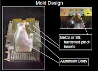
    Performance Objective Setup to generate good container welds with even, easy flash removal at target flash to container interface temperature. Mold Setup •Setup molds with carbon paper to identify even mold compression •Setup mold temperature control of 80F to 110F (25C-40C) at pinch areas to achieve container deflash interface temperature of 180F to 200F (80C to 95C) Processing Techniques •Use mold cracking timer to enable larger containers to vent upon mold opening •Use blow pin lift timer to allow container to release from mold •Insure that container releases easily from the mold –Observe for scrapes on container –Observe for flash retensionto container or mold during mold open and container extraction •Avoid heavy pinch terminations –Program parisonto light weight pinch area –Capture parisonin inflated region –Locate pinch terminations up on base to sidewall radiaway from base footprint –Option: Locate pinch terminations within the base pushup –Option: Locate one end of pinch termination within the base pushup and the other end on the container sidewall Processing Techniques •Pinch weld termination location 1.Locate pinch terminations up on base to sidewall radii away from base footprint 2.Locate pinch terminations within the base pushup 3.Locate one end of pinch termination within the base pushup and the other end on the container sidewall EASTMAN Extrusion Blow Molding Presentation.

    SCALE RATIOS

    Engineering and architectural drawing scales The recommended scales for use in engineering drawing practice and in architectural and building drawings are specified in Table 5.1.


    NOTE: If, for special applications, there is need for a larger enlargement scale or a smaller reduction scale than those shown in the table, the recommended range of scales may be extended in either direction, provided that the required scale is derived from a recommended scale by multiplying by integral powers of 10. In exceptional cases where for functional reasons the recommended scales cannot be applied, intermediate scales may be chosen.

    Australian Standard
    Technical drawing
    Part 101: General principles
    For history before 1992, see Preface.
    Second edition AS 1100.101—1992.
    PUBLISHED BY STANDARDS AUSTRALIA
    (STANDARDS ASSOCIATION OF AUSTRALIA)
    1 THE CRESCENT, HOMEBUSH, NSW 2140
    ISBN 0 7262 7806 8
    Accessed by WOODSIDE ENERGY LTD on 21 Nov 2001


  • Read more........
  • Concurrent Engineering Design

    The production process executes the final results of the design process to produce a product or system. In the pas\. the creative design process was separated from the production process. With the advent of computer modeling. this separation is no longer necessary. and the modern engineering design approach brings both proc'CSses together.
    Concurrent engineering is a nonlinear team approach to design that brings together the input. processes. and output elements necessary to produce a product. The people and processes are brought together at the very beginning. which is not normally done in the linear approach. nte team consists of design and production engineers. technicians. marketing and finance personnel. planners. and managers. who work together [0 solve a problem and produce a product.
    Many companies are finding that concurrent engineering pmcticcs result in a belter. higher-quality product. morc satisfied customers. fewer manufacturing problems. and a shorter cycle time between design initiation ,md final production.
    Figures 2.7 and 2.8 represent the concurrent approach to engineering design. based on 3-D modeling. The three intersecting circles represent the concurrent nature of this design approach. For example. in the ideation phase. design engineers interact with service technicians to ensure that the product willlJe easily serviceable by theconsumer or technician. This type of interaction results in a better prodllct for the consumer. The three intersecting circles also represent the three activities that are a major part of the conCllrrent engineering design process: ideation. refinement. and implementation. These three activities are further divided into smaller segments, as shown by the items surrounding the three circles.
    Design for manufacturabiJity (DFM) and design for assembly (OFA) practices developed out of concurrent
    engineering as an elTon to capture manufacturing and assembly knowledge up front in the imitial design
    process. This allowed engineering and manufacturing professionals 10 speak a common language that results in an optimilcd product design. OFM and OFA cvcntually cxpanded to include other practices. such as design for serviceability and design for reliability. This led to the realization that it is important to include others in the design process. such as marketing, sales. field service, finance, purchasing. and quality control.
    The center area in Figure 2.8 represenL~ the 3-D computer model and rellects the central importance of 3-D
    modeling and graphics knowledge in engineering design and production. With the use of a modeling approach. everyone on the team can have access to the current design through a computer terminal. This data sharing is critically important to the success of the design process.

    The Engineering Design Process
    Bertoline--Wiebe--Miller:
    Fundamentals of Graphics
    Communication,3/e
    The McGraw-Hill
    Companies,2001


  • Read more........
  • Design Ability

    What Designers Say The wish to design things is inherent in human beings, and design is not something that has always been regarded as needing special abilities. It is only with the emergence and growth of industrial societies that the ability to design has become regarded as a specialised talent. Although there is so much design activity going on in the world, the ways in which people design are actually rather poorly understood. It has been thought that perhaps many people possess design ability to some degree, but that only a few people have a particular design 'talent'. However, there is now a growing body of knowledge about the nature of designing, about design ability and how to develop it, and about the design process and how to improve it. When designers are asked to discuss their abilities, and to explain how they work, a few common themes emerge. One theme is the importance of creativity and intuition in design, even in engineering design. For example, the architect and engineering designer Jack Howe has said: I believe in intuition. I think that's the difference between a designer and an engineer... I make a distinction between engineers and engineering designers... An engineering designer is just as creative as any other sort of designer. Some rather similar comments have been made by the industrial designer Richard Stevens: A lot of engineering design is intuitive, based on subjective thinking. But an engineer is unhappy doing this. An engineer wants to test; test and measure. He's been brought up this way and he's unhappy if he can't prove something. Whereas an industrial designer.., is entirely happy making judgements which are intuitive. Engineering Design Methods Strategies for Product Design THIRD EDITION Nigel Cross The Open University, Mi/ton Keynes, UK JOHN WILEY & SONS, LTD Chichester- New York. Weinheim • Brisbane. Singapore. Toronto

    Computer-Aided Design and Manufacture of Injection Forging

    The design activity is responsible not only for the performance and appearance of the product but also for the cost of the component. Design, therefore, cannot be an isolated activity but must address all available manufacturing routes, with a view to optimizing the quality and cost of the component. With reference to nett-forming, the design exercise is conducted not only to specify the component-form but also to address all manufacturing constraints—machine, material, tooling, and processing conditions. Computer-aided “design for manufacture” is currently the main form of implementing of the “concurrent engineering.” To enable this, CAD/CAM is popularly used as a design approach. Using CAD/CAM approaches, simultaneous design would be effected efficiently by supporting the designer with information on all possible resources required for the design and manufacture of components. Some CAD/CAM systems [42] have demonstrated the potential for the development into decision-support systems for component/tool design. Computer-aided design and manufacture for nett-forming by injection forging is being developed as an aspect of research associated with the development of a decision-support system [64]. Methodology In order to develop a decision-support system for component/tool design using a CAD/CAM approach, several design/evaluation methods have been developed [58, 60, 64–68]. These are described briefly in the following texts. Geometric Modeling The popular strategy used for the development of the design-support systems for forging was to evolve a 2D-CAD system for component and tool design. The system was linked to a knowledge-based system to enable the evaluation of manufacturability. Subsequent to the evaluation of the geometry, the component was transferred to a CAD software to enable detailed design. This approach required the design to operate in several software environments. An integrated system, supported by solid modeling, would enable design and assessment of a component more efficiently. A solid modeling-approach—principal feature modeling—was used to enable component-design for forging within a solid modeling environment [65, 66]; the approach enables integration of currently available 2D-based knowledge-based systems. Design for manufacture requires that the component form is specified in a modular form in order to enable the evaluation of the design. The component may be defined as a combination of primitive forms as is the case in “design by features;” alternatively, the primitive forms which constitute the component may be extracted and identified automatically. Unfortunately, both these approaches are currently at a stage of refinement which only allows their applications to a limited range of component forms. Principal feature modeling [67] combines the strategies of both “design by feature” and “feature recognition” to enable efficient modeling and feature manipulation; the approach was proven to be particularly efficient for the modeling of forging/machining components [65]. Designing is attended to with reference to a prescribed set of performance requirements rather than to prescribed form features. The principal features, which represent the principal geometric profiles of a component, may be defined by the designer using arbitrary geometry—a group of curves on a plane or a curved surface. The principal features which have been generated are linked, exclusively, to a set of prescribed attributes which are catalogued in a database. COMPUTER-AIDED DESIGN, ENGINEERING, AND MANUFACTURING Systems Techniques And Applications VOLUME V I Editor CORNELIUS LEONDES Boca Raton London New York Washington, D.C. CRC Press MANUFACTURING SYSTEMS PROCESSE.

    Roughness and waviness

    A trace across a surface provides a profile of that surface which will  contain short and long wavelengths (see Figure 4.11). In order for a surface to be correctly inspected, the short and long wavelength  components need to be separated so they can be individually analysed. The long waves are to do with dimensions and the short waves are to do with the SE Both can be relevant to function but in different ways. Consider the block in Figure 6.1. This has been produced on a shaping machine. The block surface undulates in a variety of ways. There is a basic roughness, created by the tool feed marks, which is superimposed on the general plane of the surface.
    Thus, one can identify two different wavelengths, one of a small scale and one of a large scale. These are referred to as the roughness and waviness components.
    Roughness and waviness have different influences on functional performance. A good example illustrating the differences concerns automotive bodies. Considering the small-scale amplitudes and wavelengths called 'roughness', it is the roughness, not waviness, which influences friction, lubrication, wear and galling, etc. The
    next scale up from roughness is 'waviness' and it is known that the visual appearance of painted car bodies correlates more with waviness than roughness. The reason for this is the paint depth is about 100um and it has a significant filtering effect on roughness but not waviness.


    Engineering Drawing for Manufacture
    by Brian Griffiths
    Publisher: Elsevier Science & Technology Books


  • Read more........
  • DESIGNATION AND RELATIVE POSITIONS OF VIEWS

    An object positioned in space may be imagined as surrounded by six mutually perpendicular planes. So, for any object, six different views may be obtained by viewing at it along the six directions, normal to these planes. Figure 3.5 shows an object with six possible directions to obtain the different views which are designated as follows: 1. View in the direction a = view from the front 2. View in the direction b = view from above 3. View in the direction c = view from the left 4. View in the direction d = view from the right 5. View in the direction e = view from below 6. View in the direction f = view from the rear Figure 3.6a shows the relative positions of the above six views in the first angle projection and Fig.3.6b, the distinguishing symbol of this method of projection. Figure 3.7 a shows the relative position of the views in the third angle projection and Fig. 3.7b, the distinguishing symbol of this method of projection. NOTE A comparison of Figs. 3.6 and 3.7 reveals that in both the methods of projection, the views are identical in shape and detail. Only their location with respect to the view from the front is different. MACHINE DRAWING Third Edition Dr.K.I. Narayana Dr.P. Kannalah K. Venkata Reddy NEW AGE INTERNATIONAL (P) LIMITED, PUBLISHERS

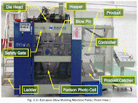
    Extrusion Blow Molding Machine Parts and Functions

    Extrusion Blow Molding Machine Parts and Functions
    • Extruder Motor—Drives the screw in the barrel to rotate and push the
    melted material into the die head.
    • Gearbox—Reduces the speed of the extruder motor into a required speed enough to push the material into the die head.
    • Hopper—A feed reservoir into which the material is loaded.
    • Extruder—A part of the machine that accepts solid resin material, conveys it in a surrounding barrel by means of a rotating screw, melts the
    material by means of heaters, and pumps it under pressure into the die
    head.
    • Cooling Fans—Cools down the barrel during machine shut down to prevent the material from degradation.
    • Heating Bands—Device attached on the barrel and the die head used to melt the solid material at a required set temperature.
    • Die Head—Used to form the melted resin into a parison and also used for adjusting the characteristics of molten resin to create a stable parison.
    • Die & Pin—Used to align the flow of parison to get a good and centered parison.
    • Hot Cutter—Cuts the parison after the mold is closed for the blowing process.
    • Blow Pin—Used to blow compressed air into the parison to inflate it after the mold has been closed and form the desired design of the mold.
    • Mold—A hollow form or a cavity into which a molten plastic material, called parison, is introduced to give the shape of the required component.
    • Deflasher—Used to cut the excess material on the bottle which is called a flash material (top and bottom).
    • Post Cooling—A part of the machine that is used to cool down the inside of the bottle, to lessen the cooling time required inside the mold.
    • Article Discharge—A part of the machine used to take the bottle out.

    Higher Institute for Plastics Fabrication
    WORKBOOK
    for
    Extrusion Blow Molding
    Practical Course
    Prepared by
    Extrusion Blow Molding Department
    1st Edition 2009


  • Read more........
  • What Is Computer-Aided Process Planning (CAPP)?

    In this section we introduce the topic of CAPP, and review important components of this technology. Chang and Wysk (1985) define process planning as “machining processes and parameters that are to be used to convert (machine) a workpiece from its initial form to a final form predetermined from an engineering drawing.” Implicit in their definition is the selection of machining resources (machine and cutting tools), the specification of setups and fixturing, and the generation of operation
    sequences and numerical control (NC) code. Traditionally, the task of process planning is performed by a human process planner with acquired expertise in machining practices who determines from a part’s engineering drawings what the machining requirements are.

    Manual process planning has many drawbacks. In particular, it is a slow, repetitive task that is  prone to error. With industry’s emphasis on automation for improved productivity and quality, computerized CAD and computer-aided manufacturing (CAM) systems which generate the data for driving computer numerical control (CNC) machine tools, are the state-of-the-art. Manual process planning in this context is a bottleneck to the information flow between design and manufacturing.

    CAPP is the use of computerized software and hardware systems for automating the process planning task. The objective is to increase productivity and quality by improving the speed and accuracy of process planning through automation of as many manual tasks as possible. CAPP will increase automation and promote integration among the following tasks:
    1. Recognition of machining features and the construction of their associated machining volumes from a geometric CAD model of the part and workpiece
    2. Mapping machining volumes to machining operations
    3. Assigning operations to cutting tools
    4. Determining setups and fixturing
    5. Selecting suitable machine tools
    6. Generating cost-effective machining sequences
    7. Determining the machining parameters for each operation
    8. Generating cutter location data and finally NC machine code
    Traditionally, CAPP has been approached in two ways. These two approaches are variant process planning and generative process planning. In the following section we discuss these and other issues in a review of work in this field.

    THE
    MECHANICAL
    SYSTEMS
    DESIGN
    HANDBOOK
    Modeling, Measurement,
    and Control
    OSITA D. I. NWOKAH
    YILDIRIM HURMUZLU
    Southern Methodist University
    Dallas, Texas
    CRC PRESS
    Boca Raton London New York Washington, D.C.


  • Read more........
  • Polymer molding

    Thermoplastics are molded as viscous liquids. Injection molding and extrusion dominate, but all molding processes impose flow that can orientate the molecules; if the molding is cooled fast enough the alignment is frozen in (Figure 19.5).
    If not, polymers mostly prefer to form an amorphous structure. In some polymers crystallinity may develop on slow cooling. All polymers shrink as the mold cools from the molding temperature to room temperature because of thermal contraction and the loss of free volume caused by crystallization. Allowance must be made for this when the mold is designed.
    Materials
    Engineering, Science,
    Processing and Design
    Michael Ashby, Hugh Shercliff and David Cebon
    University of Cambridge,
    UK
    AMSTERDAM • BOSTON • HEIDELBERG • LONDON • NEW YORK • OXFORD
    PARIS • SAN DIEGO • SAN FRANCISCO • SINGAPORE • SYDNEY • TOKYO
    Butterworth-Heinemann is an imprint of Elsevier


  • Read more........
  • Design Process

    Before any discussion of CAD, it is necessary to understand the design process in general (Fig. 3). What are the series of events that lead to the beginning of a design project? How does the engineer go about the process of designing something? How does one arrive at the conclusion that the design has been completed? We address these questions by defining the process in terms of six distinct stages: 1. Customer input and perception of need 2. Problem definition 3. Synthesis 4. Analysis and optimization 5. Evaluation 6. Final design and specification A need is usually perceived in one of two ways. Someone must recognize either a problem in an existing design or a customer-driven opportunity in the marketplace for a new product. In either case, a need exists which can be addressed by modifying an existing design or developing an entirely new design. Because the need for change may only be indicated by subtle circumstances—such as noise, marginal performance characteristics, or deviations from quality standards—the design engineer who identifies the need has taken a first step in correcting the problem. That step sets in motion processes that may allow others to see the need more readily and possibly enroll them in the solution process. Mechanical Engineers’ Handbook: Materials and Mechanical Design, Volume 1, Third Edition. Edited by Myer Kutz by John Wiley & Sons, Inc.

    Variations and Extension to the Injection-Molding Process

    Injection Blow Molding.
    A preform (this looks like a test tube with bottle cap threads) is injection molded in one cavity, removed and then placed into another where it is pressurized with gas to stretch the hot preform into a thinnerwalled
    seamless bottle or container such as a milk bottle or gas tank. This is depicted in Figure 7. This is an extension of injection molding more than a variation.

    Injection Compression/Coining.
    With this technique the mold is only partially closed during injection. At the appropriate time and with the right amount of plastic in the mold, the clamp is then completely closed, forcing (compressing) the plastic to the shape of the mold cavity. A variation on this is coining.
    The clamp is closed but the mold has components that compress the plastic in the cavity as the plastic cools. Coining is where the cavity volume is changing during the solidification of the plastic. Plastic is injected into the cavity and then the movable platen closes completely, or a mold component moves to compress the plastic to compensate for shrinkage or densification.

    Gas-Assist Injection Molding.
    Here, plastic is injected into the cavity until it is 50–85% full, then high pressure gas, usually nitrogen, is  injected to finish filling the cavity by pushing the plastic flow front to the end of the cavity. This leaves a gas bubble or channel inside the part. This saves plastic, reduces cost, and often improves part strength especially in thick sections. Gas can be injected at the nozzle of the machine or directly into the mold as depicted in Figure 8. Gas-assist molding can be considered as a variation of co-injection molding where the outer layer or skin of the part is plastic and the core is a gas channel rather than another type of plastic.

    “Injection Molding” in EPSE 2nd ed., Vol. 8, pp. 102–138, by I. I. Rubin,Robinson Plastic Corp.
    JOHN W. BOZZELLI
    Midland, Michigan


  • Read more........
  • Extrusion

    General Features of Single Screw Extrusion
    One of the most common methods of processing plastics is Extrusion using a screw inside a barrel as illustrated in Fig. 4.1. The plastic, usually in the form of granules or powder, is fed from a hopper on to the screw. It is then conveyed along the barrel where it is heated by conduction from the barrel heaters and shear due to its movement along the screw flights. The depth of the screw channel is reduced along the length of the screw so as to compact the material. At the end of the extruder the melt passes through a die to produce an extrudate of the desired shape. As will be seen later, the use of different dies means that the extruder screwharrel can be used as the basic unit of several processing techniques.

    PLASTICS
    ENGINEERING
    Third Edition
    R.J. Crawford, BSc, PhD, DSc, FEng, FIMechE, FIM
    Department of Mechanical, Aeronautical
    and Manufacturing Engineering
    The Queen’s University of Belfast
    l E I N E M A N N
    OXFORD AMSTERDAM BOSTON LONDON NEW YORK PARIS
    SAN DlEGO SAN FRANCISCO SINGAPORE SYDNEY TOKYO


  • Read more........
  • Drawing Number

    The drawing number is used for part identification and to ease storage and retrieval of the drawing and the produced parts. While there is no set way to assign part numbers, common systems are nonsignificant, significant, or some combination of the two previous systems.
    Nonsignificant numbering systems are most preferred because no prior knowledge of significance is required.
    Significant numbering systems could be used for commonly purchased items like fasteners. For example, the part number for a washer could include the inside diameter, outside diameters, thickness, material, and plating.
    A combination of nonsignificant and significant numbering systems may use sections of the numbers in a hierarchical manner. For example, the last three digits could be the number assigned to the part (001, 002, 003, etc.). This would be nonsignificant. The remaining numbers could be significant: two numbers could be the model variation, the next two numbers could be the model number, and the next two could be the series number while the last two could be the project number. Many other possibilities exist.
    Dimensioning and Tolerancing
    Handbook
    Paul J. Drake, Jr.
    McGraw-Hill
    New York San Francisco Washington , D.C. Auckland Bogata
    Caracas Lisbon London Madrid Mexico City Milan
    Montreal New Delhi San Juan Singapore
    Sydney Tokyo Toronto


  • Read more........
  • DEFINING PLASTIC PART REQUIREMENTS -2

    Weather Resistance Temperature, moisture, and UV sun exposure affect plastic parts’ properties and appearance. The end-use of a product determines the type of weather resistance required. For instance, external automotive parts such as mirror housings must withstand continuous outdoor exposure and perform in the full range of weather conditions. Additionally, heat gain from sun on dark surfaces may raise the upper temperature requirement considerably higher than maximum expected temperatures. Conversely, your requirements may be less severe if your part is exposed to weather elements only occasionally. For example, outdoor Christmas decorations and other seasonal products may only have to satisfy the requirements for their specific, limited exposure. Radiation A variety of artificial sources — such as fluorescent lights, high-intensity discharge lamps, and gamma sterilization units — emit radiation that can yellow and/or degrade many plastics. If your part will be exposed to a radiation source, consider painting it, or specifying a UV-stabilized resin. Appearance Aesthetic requirements can entail many material and part-design issues. For example, a need for transparency greatly reduces the number of potential plastics, especially if the part needs high clarity. Color may also play an important role. Plastics must often match the color of other materials used in parts of an assembly. Some applications require the plastic part to weather at the same rate as other materials in an assembly. Engineering Polymers Part and Mold Design THERMOPLASTICS A Design Guide Bayer Corporation • 100 Bayer Road • Pittsburgh http://www.bayer.com/polymers-usa

    Oblique projection

    In oblique projection, the object is aligned such that one face (the front face) is parallel to the picture plane. The projection lines are still parallel but they are not perpendicular to the picture plane.
    This produces a view of the object that is 3D. The front face is a true view (see Figure 2.7). It has the advantage that features of the front face can be drawn exactly as they are, with no distortion. The receding faces can be drawn at any angle that is convenient for illustrating the shape of the object and its features. The front face will be a true view, and it is best to make this one the most complicated of the faces. This makes life easier! Most oblique projections are drawn at an angle of 45 ~ and at this angle the foreshortening is 50%. This is called a Cabinet projection. This is because of its use in the furniture industry. If the 45 ~ angle is used and there is no foreshortening it is called a Cavalier projection. The problem with Cavalier projection is that, because there is no foreshortening, it looks peculiar and distorted. Thus, Cabinet projection is the preferred method for constructing an oblique projection.
    An oblique drawing of the bearing bracket in Cabinet projection is shown in Figure 2.8. For convenience, the front view with circles was chosen as the true front view. This means that the circles are true circles and therefore easy to draw. The method of construction for oblique projection is similar to the method described above for isometric projection except that the angles are not 30 ~ but 45 ~ .
    Enclosing rectangles are again used and transposed onto the 45 ~ oblique planes using 50% foreshortening.


    Engineering Drawing for Manufacture
    by Brian Griffiths
    Publisher: Elsevier Science & Technology Books


  • Read more........
  • Critical Role of Computers in Modern Manufacturing

    A number of steps are involved in manufacturing a part from its conceptualization to production. They include product design, process planning, production system design, and process control. Computers are used extensively in all these stages to make the entire process easier and faster. Potential benefits of using computers in manufacturing include reduced costs and lead times in all engineering design stages, improved quality and accuracy, minimization of errors and their duplication, more efficient analysis tool, and accurate control and monitoring of the machines/processes, etc. Some of the applications of computers in manufacturing are shown in Figure 1.5. In computeraided design (CAD), computers are used in the design and analysis of the products and processes. They play a critical role in reducing lead time and cost at the design stages of the products/process. Also, computers may be utilized to plan, manage, and control the operations of a manufacturing system: computer-aided manufacturing (CAM) (Bedworth, Handerson, and Wolfe, 1991). In CAM, computers are either used directly to control and monitor the machines/processes (in real-time) or used off-line to support manufacturing operations such as computer-aided process planning (CAPP) or planning of required materials. At higher levels, computers are utilized in support of management. They play a critical role in all stages of decision making and control of financial operations by processing and analyzing data and reporting the results (management information systems, MIS) (Hollingam, 1987). Computers facilitate integration of CAD, CAM, and MIS (computer-integrated manufacturing, CIM) (Vajpayee, 1995) (see Figure 1.5). They provide an effective communication interface among engineers, design, management, production workers, and project groups to improve efficiency and productivity of the entire system. THE MECHANICAL SYSTEMS DESIGN HANDBOOK Modeling, Measurement, and Control OSITA D. I. NWOKAH YILDIRIM HURMUZLU Southern Methodist University Dallas, Texas CRC PRESS Boca Raton London New York Washington, D.C.

    FORMING - DRILLING - REAMING - BORING

    FORMING
    Forming is the process of turning convex, or concave or of any irregular shape. Form turning may be accomplished by the following methods:
    1.using a forming tool
    2.combining cross-land longitudinal feed.
    3.tracing or coping a template.

    DRILLING
    Drilling is the operation of producing a cylindrical hole in a work piece by the rotating cutting edge of a cutter known as drill.

    REAMING
    Reaming is a process of finishing and sizing a hole, which has been drilled or bored. The tool used is called reamer, which has multiple cutting edges. The reamer is held on tailstock spindle, either direct or through a drill chucks and is held stationary while the work is revolved at a very low speed. The feed varies from 0.5 to 2mm per revolution.

    BORING
    Boring is the operation of enlarging and truing a hole produced by drilling, punching, casting or forging.
    1.The work is revolved in a chuck or a faceplate and the tool, which is fitted to the tool post, is fed in to the work.
    2.The work is clamped on the carriage and a boring bar holding the tool is supported between the centers and made to revolve.
    fr. NTTF ( NETTUR TECHNICAL TRAINING FOUNDATION)


  • Read more........
  • Torsion

    A bar is under torsional stress when it is held fast at one end, and a force acts at the other end to twist the bar. In a round bar (Fig. 4.9) with a constant force acting, the straight-line ab becomes the helix ad, and a radial line in the cross-section, ob, moves to the position ad. The angle bad remains constant while the angle bod increases with the length of the bar. Each cross section of the bar tends to shear off the one adjacent to it, and in any cross section the shearing stress at any point is normal to a radial line drawn through the point. Within the shearing proportional limit, a radial line of the cross section remains straight after the twisting force has been applied, and the unit shearing stress at any point is proportional to its distance from the axis.
    The twisting moment, T, is equal to the product of the resultant, P, of the twisting forces, multiplied by its distance from the axis, p. Resisting moment, T,, in torsion, is equal to the sum of the moments of the unit
    shearing stresses acting along a cross section with respect to the axis of the bar. If d A is an elementary area of the section at a distance of z units from the axis of a circular shaft [Fig. 4.9 (b)], and c is the distance from
    the axis to the outside of the cross section where the unit shearing stress is Z, then the unit shearing stress acting on dA is (ZZ/C) dA, its moment with respect to the axis is (zz2/c) dA, and the sum of all the moments
    of the unit shearing stresses on the cross section is f (rz2/c) dA. In this expression the factor fz2 dA is the polar moment of inertia of the section with respect to the axis. Denoting this by J the resisting moment may be written zJ/c.
    The polar moment of inertia of a surface about an axis through its center of gravity and perpendicular to the surface is the sum of the products obtained by multiplying each elementary area by the square of its distance from the center of gravity of its surface; it is equal to the sum of the moments of inertia taken with respect to two axes in the plane of the surface at right angles to each other passing through the center of gravity section of a round shaft.
    The analysis of torsional shearing stress distribution along noncircular cross sections of bars under torsion is complex. By drawing two lines at right angles through the center of gravity of a section before twisting,
    and observing the angular distortion after twisting, it has been found from many experiments that in noncircular sections the shearing unit stresses are not proportional to their distances from the axis. Thus in a rectangular bar there is no shearing stress at the comers of the sections, and the stress at the middle of the wide side is greater than at the middle of the narrow side. In an elliptical bar the shearing stress is greater along the flat side than at the round side.

    Plastics
    Engineered
    Product
    Design
    Dominick Rosato and
    Donald Rosato
    ELSEVIER


  • Read more........
  • Insulated Runners

    The insulated runner system (Figure 41) allows the molten polymer to flow into the runner, and then cool to form an insulating layer of solid plastic along the walls of the runner. The insulating layer reduces the diameter of the runner and helps maintain the temperature of the molten portion of the melt as it awaits the next shot. The insulated runner system should be designed so that, while the runner volume does not exceed the cavity volume, all of the molten polymer in the runners is injected into the mold during each shot. This full consumption is necessary to prevent excess build-up of the insulating skin and to minimize any drop in melt temperature. The many advantages of insulated runner systems, compared with conventional runner systems, include: • Less sensitivity to the requirements for balanced runners. • Reduction in material shear. • More consistent volume of polymer per part. • Faster molding cycles. • Elimination of runner scrap – less regrind. • Improved part finish. • Decreased tool wear. However, the insulated runner system also has disadvantages. The increased level of technology required to manufacture and operate the mold results in: • Generally more complicated mold design. • Generally higher mold costs. • More difficult start-up procedures until running correctly. • Possible thermal degradation of the polymer melt. • More difficult color changes. • Higher maintenance costs. Product and Mold Design d9b604f1c18a4896b020a210866ec775.

    Standards ANSI ISO

    Standards If a machinist in a machine shop in a remote location is required to make a part for a US-built commercial aircraft, he or she must understand the drawings. This requires worldwide, standardized drafting practices. Many countries support a national standards development effort in addition to international participation. In the United States, the two groups of standards that are most influential are developed by the standards development bodies administered by the American National Standards Institute (ANSI) and the International Organization for Standardization (ISO). See Chapter 6 for a comparison of US and ISO standards. ANSI The ANSI administers the guidelines for standards creation in the United States. The American Society of Mechanical Engineers sponsors the development of the Y14 series of standards. The 26 standards in the series cover most facets of engineering drawings and related documents. Many of the concepts about how to read an engineering drawing presented in this chapter come from these standards. In addition to the Y14 series of standards, the complete library should also possess the B89 Dimensional Measurement standards series and the B46 Surface Texture standard. ISO The ISO, created in 1946, helped provide a structure to rebuild the world economy (primarily Europe) after World War II. Even though the United States has only one vote in international standards development, the US continues to propose many of the concepts presented in the ISO drafting standards. Dimensioning and Tolerancing Handbook Paul J. Drake, Jr. McGraw-Hill New York San Francisco Washington , D.C. Auckland Bogata Caracas Lisbon London Madrid Mexico City Milan Montreal New Delhi San Juan Singapore Sydney Tokyo Toronto

    Linear and angular dimensioning

    The latest ISO standard concerned with dimensioning is ISO 129"1985. However, it is known that a new one is soon to be published which is ISO 129 Part 1 (the author sits on BSI/ISO committees and has seen the draft new standard). It has been through all the committee approval stages and has been passed for publication. However, it is being held back, awaiting the approval of a Part 2 so that they can be published together. The BSI estimates the publication date will be 2003, hence it will be ISO 129-1:2003.
    There have been versions prior to 1985 and each has defined slightly different dimensioning conventions. Needless to say, the 2003 convention gives a slightly different convention to the 1985 one! Throughout this section, the 2003 convention will be presented so that readers are prepared for the latest version. Figure 4.3 shows a hypothetical spool valve that is defined by 14 dimensions in which 12 are linear and two angular. The valve is shown using the ISO principles of line thickness described in
    Chapter 3. Note that the valve outline uses the ISO type 'A' thickness whereas the other lines (including the dimension lines) are the ISO type 'B' thin lines. The outline thus has more prominence than the other lines and hence the valve tends to jump out of the drawing page and into the eye of the reader. The valve dimensions
    follow the dimensioning convention laid down in the future ISO 129-1:2003 standard. Tolerances have been left off the figure for convenience. In this case there are two datum features. The first is the left-hand annular face of the largest cylindrical diameter, i.e. the face with the 30 ~ chamfer. Horizontal dimensions associated
    with this datum face use a terminator in the form of a small circle.
    The other datum feature is the centre rotational axis of the spool valve represented by the chain dotted line. All the extension lines touch the outline of the spool valve. The dimension values are normally placed parallel to their dimension line, near the middle, above and clear of it. Dimension values should be placed in such a
    way that they are not crossed or separated by any other line.

    Engineering Drawing for Manufacture
    by Brian Griffiths
    Publisher: Elsevier Science & Technology Books


  • Read more........
  • Cold Slug Wells

    At all runner intersections, the primary runner should overrun the  secondary runner by a minimum distance equal to one diameter, as shown in Figure 39. This produces a feature known as a melt trap or cold slug well. Cold slug wells improve the flow of the polymer by catching the colder, higher-viscosity polymer moving at the forefront of the molten mass and allowing the following, hot, lower-viscosity polymer to flow more readily into the mold-cavity.
    The cold slug well thus prevents a mass of cold material from entering the cavity and adversely affecting the final properties of the finished part.


  • READ MORE.......

  •