
Oblique projection
Structural foam molding

Isometric projection

In isometric projection, the projection plane forms three equal angles with the co-ordinate axis. Thus, considering the isometric cube in Figure 2.4, the three cube axes are foreshortened to the same amount, i.e. AB = AC = AD. Two things result from this, firstly, the angles a = b = 30 ~ and secondly, the rear (hidden) corner of the cube is coincident with the upper corner (corner D). Thus, if the hidden edges of the cube had been shown, there would be dotted lines going from D to F, D to C and D to B. The foreshortening in the three axes is such that AB = AC = AD = (2/3) o.5 = 0.816. Since isometric projections are pictorial projections and dimensions are not normally taken from them, size is not really important. Hence, it is easier to ignore the foreshortening and just draw the object full size. This makes the drawing less complicated but it does have the effect of apparently enlarging the object by a factor 1.22 (1 + 0.816). Bearing this in mind and the fact that both angles are 30 ~ it is not surprising that isometric projection is the most commonly used of the three types of axonometric projection.
The method of constructing isometric projections is shown in the diagrams in Figures 2.5 and 2.6. An object is translated into isometric projection by employing enclosing shapes (typically squares and rectangles) around important features and along the three axes. Considering the isometric cube in Figure 2.4, the three sides are three squares that are 'distorted' into parallelograms, aligned with the three isometric axes. Internal features can be projected from these three parallelograms.
The method of constructing an isometric projection of a flanged bearing block is shown in Figure 2.5. The left-hand drawing shows the construction details and the right-hand side shows the 'cleaned up' final isometric projection. An enclosing rectangular cube could be placed around the whole bearing block but this enclosing rectangular cube is not shown on the construction details diagram because of the complexity. Rather, the back face rectangle CDEF and the bottom face ABCF are shown. Based on these two rectangles, the construction method is as follows. Two shapes are drawn on the isometric back plane CDEE These are the base plate rectangle CPQF and the isometric circles within the enclosing square LMNO. Two circles are placed within this enclosing square. They represent the outer and inner diameters of the bearing at the back face.
The method of constructing an isometric circle is shown in the example in Figure 2.6. Here a circle of diameter ab is enclosed by the square abcd. This isometric square is then translated onto each face of the isometric cube. The square abcd thus becomes a parallelogram abcd. The method of constructing the isometric circles
within these squares is as follows. The isometric square is broken down further into a series of convenient shapes, in this case five small long-thin rectangles in each quadrant. These small rectangles are then translated on to the isometric cube. The intersection heights ef, gh, ij and kl are then projected onto the equivalent
rectangles on the isometric projection. The dots corresponding to the points fhjl are the points on the isometric circles. These points can be then joined to produce isometric circles. The isometric circles can either be produced freehand or by using matching ellipses. Returning to the isometric bearing plate in Figure 2.5, the
isometric circles representing the bearing outside and inside diameters are constructed within the isometric square LMNO. Two angled lines PR are drawn connecting the isometric circles to the base CPQE The rear shape of the bearing bracket is now complete within the enclosing rectangle CDEE Returning to the isometric projection drawing of the flanged bearing block in Figure 2.5. The inside and outside bearing diameters in the isometric form are now projected forward and parallel to the axis BC such that two new sets of isometric circles are constructed as shown. The isometric rectangle CPQF is then projected forward, parallel to BC that produces rectangle ABST, thus completing the bottom plate of the bracket. Finally, the web front face UVWX is constructed. This completes the various constructions of the isometric bearing bracket and the final
isometric drawing on the right-hand side can be constructed and hidden detail removed. Any object can be constructed as an isometric drawing provided the above rules of enclosing rectangles and squares are followed which are then projected onto the three isometric planes.
Engineering Drawing for Manufacture
by Brian Griffiths
Publisher: Elsevier Science &
Technology Books
The raw material for plastic products

Types of drawings

Product Development Organizations

References and Bibliography
Many current resources are available on the Internet via www.ulrich-eppinger.net Stage-gate product development processes have been dominant in manufacturing firms for the past 30 years. Cooper describes the modem stage-gate process and many of its enabling practices. Cooper, Robert G., Winning at New Products: Accelerating the Process from Idea to Launch, third edition, Perseus Books, Cambridge, MA, 2001.
Plastic Manufacturing Process

The AMF Development Process

References and Bibliography
Many current resources are available on the Internet via www.ulrich-eppinger.net Stage-gate product development processes have been dominant in manufacturing firms for the past 30 years. Cooper describes the modem stage-gate process and many of its enabling practices. Cooper, Robert G., Winning at New Products: Accelerating the Process from Idea to Launch, third edition, Perseus Books, Cambridge, MA, 2001.
additives

Product Development Process Flows
Thermosetting

Complex Systems

Examples of thermoplastics and their characteristics

Examples several types of thermoplastic with the characteristics.
- Poly Vinyl Chlorid (PVC)
Material properties:
a. Hard PVC
Thermoplastic, hard, rigid, transparent, capable of welding and glueing. Resistant to oil, acids, language, alcohol, but less resistant to solvents such as acetone, benzol, esters, temperature resistant up to 80 ° C.
b. Soft PVC
Greatly influenced by the amount of material given the softness softener that occur from such skin becomes rubbery. Clay, crack resistant, capable of being used to a temperature of 80 ° C, while the resistance to chemical solution under the hard PVC.
- Poly Styrol (PS)
Thermoplastics, such as glass, easy to be colored, at room temperature is relatively hard and rigid. Odorless and flammable, resistant to water, acids, bases, alcohols, oils but soluble in benzol, gasoline, acetone, ether. Can be glued and welded.
- Poly Methyl Metha Crylat (PMMA)
Thermoplastic, hard, brittle, scratch resistant, looks like glass, translucent, wear resistant, lightweight, easy to be colored, odorless, resistant to mild acids, alkalis, gasoline and oil, but not resistant to solvents.
- Poly Ethilen (PE)
Thermoplastic, soft material, clay, capable of working up to -40 ° C, low water absorption, resistant to acids, bases, solvents, alcohol, gasoline, water, oil, but do not hold HcIO and flammable.
- Polyamide (PA)
The name of the market is Nylon, thermoplastic properties, ductile at 2% -3% humidity, hard, brittle and stiff in the dry state. Color yellowish, opaque and easily colored. Able welded and glued also able to work on - ^ 40 ° C - 110 ° C.
- Polycarbonate (PC)
Thermoplastics, such as glass, capable of bouncer, capable of machining high, the shape does not change until heated at a temperature of 135 ° C, non-flammable, resistant to acids software (not concentrated), oil, gasoline and alcohol, are not resistant to alkali and solvents.
- Silicone (Si)
Heat resistant, have physical and chemical properties are very good, waterproof, capable diginakan at -90 ° C - 250 ° C, insulation material, material loading compactor for high humid areas.
- Polyurethane (PUR)
Is Elastomere, elastic like rubber, rub-resistant, scratch resistant, can be used at a temperature of -30 ° C - 80 ° C, resistant to oil, fuel, not acid resistant, alkali, solvents, hot water and flammable.
- Epoxydeharze
Elastomere, until light golden yellow color, hard and easy to work with machinery, resistant to weather changes and can be used up to 110 ° C, high electrical pengisolir, hold the soft acid, alkaline alcohol, oil, solvents, soluble in acetone and the Flammable .
for STEP BY STEP GUIDE solidwork simple tutorial please visit.........
www.solidworksimpletutorial.blogspot.com
---or---
Quick-Build Products

References and Bibliography
Many current resources are available on the Internet via www.ulrich-eppinger.net
Stage-gate product development processes have been dominant in manufacturing firms for the past 30 years. Cooper describes the modem stage-gate process and many of its enabling practices.
Cooper, Robert G., Winning at New Products: Accelerating the Process from Idea to Launch, third edition, Perseus Books, Cambridge, MA, 2001.
Thermoplastic materials

Amorphous polymers do not have a specific melting point. At low temperatures they are hard, dense, brittle and luster, at high temperatures such as rubber or leather. Temperature when the transition occurs is called the Glass-Transition Temperature (Tg), also called Point glass or glass temperature.
In Crystaline material, regular molecular chain structure and become active only after the material is heated to its melting point. This means that these materials do not pass through a phase softened, but remained solid until heated at certain temperature and instantly melted material.
Differences property amorphous and Crystaline
Amorphous
* Net
* Low Shrinkage
* Softened
* The high mashed
* Lack of chemical resistant
Crystaline
* Opaque
* Depreciation high
* Melt
* Low Power mashed
* Hold chemicals
Examples of materials based on molecular structure
Amorphous
* ABS
* Acrylic
* Polyamide
* Polyacrylate
* Polycarbonate
* Polystyrene
* Polyurethane
Crystaline
* Acetal
* Nylon
* Polyester (PBT)
* Polyethylene
* Polyethyleneterephthalate (PET)
* Polypropylene
* Polyvinylcloride (PVC)
To improve the ductile properties of amorphous glass below its transition temperature we can mix it with some elastomers. This is known as an elastomer polymers dimodofikasi into rubber. Some examples of the elastomer is Acrylates, Butyls, Fluorosilicon, Fuorocarbons Polysulfids polyurethane.
The ability of plastics to return to his native structure after heating and then softened or melted in other words, reversible process called Thermoplastic. If we raise the temperature above the Tg of his skin then first became such as rubber along with the addition of temperature. finally at a temperature above its melting point at Crystaline become viscous fluid with a viscosity decreases with further increase in temperature. In the liquid phase resembles a plastic ice cream can be formed. Because of its recyclable plastic can then be formed up to several times, but repetition of heating and cooling causes the reduction in the quality of the plastic.
When Thermoplastic deformed or are interested, this process is called orientation. Like the metal polymer becomes anisotropic. Specimens become more powerful and solid in the direction of pull than the transverse direction. Another important thing is the ability of water-absorbing polymer. Water makes the plastic becomes more plastic. With the addition of moisture, Glasstransition Temperature, voltage and modulus of elasticity will be lower. Dimensional changes also occur due to moisture environment.
(Bid / multiple sources)
High-Risk Products

The product development process addresses many types of risk. These include technical
risk (Will the product function properly?), market risk (Will customers like what the team
develops?), and budget and schedule risk (Can the team complete the project on time an
within budget?). High-risk products are those that entail unusually large uncertainties related
to the technology or market so that there is substantial technical or market risk. The generic product development process is modified to face high-risk situations by taking steps to address the largest risks in the early stages of product development. This usually requires completing some design and test activities earlier in the process. For example, when there is great uncertainty regarding customer acceptance of a new product, concept testing using renderings or user-interface prototypes may be done very early in the process in order to reduce the market uncertainty and risk. If there is high uncertainty related to technical performance of the product, it makes sense to build working models of the key features and to test these earlier in the process. Multiple solution paths may be explored in parallel to ensure that one of the solutions succeeds. Design reviews must assess levels of risk on a regular basis, with the expectation that risks are being reduced over time and not being postponed.
References and Bibliography
Many current resources are available on the Internet via www.ulrich-eppinger.net
Stage-gate product development processes have been dominant in manufacturing firms for the past 30 years. Cooper describes the modem stage-gate process and many of its enabling practices.
Cooper, Robert G., Winning at New Products: Accelerating the Process from Idea to Launch, third edition, Perseus Books, Cambridge, MA, 2001.
for STEP BY STEP GUIDE solidwork simple tutorial please visit.........
www.solidworksimpletutorial.blogspot.com
---or---
basic theory of plastic

Plastic is an organic material formed from macromolecules and processed through a chemical process or through the synthesis of other materials. The word itself comes from the plastic plastikos (Greek) which means it can be formed. Plastics can be formed, cast or merged with another with relative ease. Plastic itself commercially daiam various forms of sheets, plates, film, rolls, and tube granulat with various cross-sectional shape. Polymer word was first used in 1866. Previous polymers made from natural organic material of animals and plants. With a variety of chemical reactions in the modified cellulose acetate cellulose, is used to for the manufacture of photographic film, sheet packaging, and textile fibers. Cellulose nitrate is also converted into cellulose for plastics, explosives, rayon and varnished. The first synthetic polymers which man is phenol-formaldehyde, a type of thermoset that was developed in 1906 called bakelit rian (the commercial name, LH Backeland, 1863-1944)
The development of modern plastics technology began in 1920, when the raw materials needed to manufacture the polymer material is then extracted from the tin and petroleum. Ethylene is the first example of such nentah materials, and the forming polyethylene block. Ethylene is a product of the reaction between acetylen with hydrogen, while acetylen is the result of reaction between coke and methane. Similarly, polypropylene, Polyvinylchlonde, Polymethyl methacrylate, polycarbonate and others made the same way. These materials are known as synthetic organic polymer. Although in Polyethylene only Carbon and Hydrogen atoms are involved, other polymers can be combined with chlorine, Florin, sulfur, silicon, nitrogen and oxygen. The result is to make the other advantages of each polymer.
The reason people use plastic materials as a basic material goods / tools are:
- Easily carried or formed
- Do not conduct electricity
- Able to pull a fairly high
- Low specific gravity
- Etc.
When compared to metal, plastic has advantages and disadvantages as follows;
1. Profit
a. Mild
b. Economical in progress
c. Corrosion-resistant
d. Vibration damping
e. Low heat dissipation
f. Surface / better display. Can be recycled (except type termosett). Complex formation can be manufactured
2. Loss
a. Low strength
b. Low thermal resistance
c. Dimensions are not Stable
d. Easy to change nature.
e. Difficult repairs.
f. More suitable for mass production
g. For some types of polymers are still expensive.
( bid / multiple sources )
for STEP BY STEP GUIDE solidwork simple tutorial please visit.........
www.solidworksimpletutorial.blogspot.com
---or---
Process-Intensive Products

Examples of process-intensive products include semiconductors, foods, chemicals, and
paper. For these products, the production process places strict constraints on the properties of the product, so that the product design cannot be separated, even at the concept phase, from the production process design. In many cases, process-intensive products are produced in very high volumes and are bulk, as opposed to discrete, goods.
In some situations, a new product and new process are developed simultaneously. For
example, creating a new shape of breakfast cereal or snack food will require both product and process development activities. In other cases, a specific existing process for making the product is chosen in advance, and the product design is constrained by the capabilities of this process. This might be true of a new paper product to be made in a particular paper mill or a new semiconductor device to be made in an existing wafer fabrication facility.
References and Bibliography
Many current resources are available on the Internet via www.ulrich-eppinger.net
Stage-gate product development processes have been dominant in manufacturing firms for the past 30 years. Cooper describes the modem stage-gate process and many of its enabling practices.
Cooper, Robert G., Winning at New Products: Accelerating the Process from Idea to Launch, third edition, Perseus Books, Cambridge, MA, 2001.
for STEP BY STEP GUIDE autocad simple tutorial please visit.........
www.autocadsimpletutorial.blogspot.com
---or---
French's model of the design process

The process begins with an initial statement of a need, and the first design activity is analysis of the problem. French suggests that the analysis of the problem is a small but important part of the overall process. The output is a statement of the problem, and this can have three elements:
• a statement of the design problem proper
• limitations placed upon the solution, e.g. codes of practice, statutory requirements, customers' standards, date of completion, etc.
• the criterion of excellence to be worked to.
Engineering Design Methods
Strategies for Product Design
THIRD EDITION
Nigel Cross
The Open University, Mi/ton Keynes, UK
JOHN WILEY & SONS, LTD
Chichester- New York. Weinheim • Brisbane. Singapore. Toronto
for STEP BY STEP GUIDE unigraphics simple tutorial please visit.........
www.unigraphicsimpletutorial.blogspot.com
---or---
Platform Products

A platform product is built around a preexisting technological subsystem (a technology platform). Examples of such platforms include the tape transport mechanism in the Sony Walkman, the Apple Macintosh operating system, and the instant film used in Polaroid cameras. Huge investments were made in developing these platforms, and therefore every attempt is made to incorporate them into several different products. In some sense, platformproducts are very similar to technology -push products in that the team begins the development effort with an assumption that the product concept will embody a particular technology. The primary difference is that a technology platform has already demonstrated its usefulness in the marketplace in meeting customer needs. The firm can in many cases assume that the technology will also be useful in related markets. Products built on technology platforms are much simpler to develop than if the technology were developed from scratch. For this reason, and because of the possible sharing of costs across several products, a firm may be able to offer a platform product in markets that could not justify the development of a unique technology.
References and Bibliography
Many current resources are available on the Internet via www.ulrich-eppinger.net
Stage-gate product development processes have been dominant in manufacturing firms for the past 30 years. Cooper describes the modem stage-gate process and many of its enabling practices.
Cooper, Robert G., Winning at New Products: Accelerating the Process from Idea to Launch, third edition, Perseus Books, Cambridge, MA, 2001.
for STEP BY STEP GUIDE solidwork simple tutorial please visit.........
www.solidworksimpletutorial.blogspot.com
---or---
The Design Process Descriptive Models

There have been many attempts to draw up maps or models of the design process. Some of these models simply describe the sequences of activities that typically occur in designing; other models attempt to prescribe a better or more appropriate pattern of activities.
Descriptive models of the design process usually identify the significance of generating a solution concept early in the process, thus reflecting the solution-focused nature of design thinking. This initial solution conjecture is then subjected to analysis, evaluation,refinement and development. Sometimes, of course, the analysis and evaluation show up fundamental flaws in the initial conjecture and it has to be abandoned, a new concept generated and the cycle started again. The process is heuristic: using previous experience, general guidelines and rules of thumb that lead in what the designer hopes to be the right direction, but with no absolute guarantee of success.
In Chapter 1 I developed a simple descriptive model of the design process, based on the essential activities that the designer performs. The end-point of the process is the communication of a design, ready for manufacture. Prior to this, the design proposal is subject to evaluation against the goals, constraints and criteria of the design brief. The proposal itself arises from the generation of a concept by the designer, usually after some initial exploration of the ill-defined problem space. Putting these four activity types in their natural sequence, we have a simple four-stage model of the design process consisting of: exploration, generation, evaluation and communication.
This simple four-stage model is shown diagrammatically in Figure 9. Assuming that the evaluation stage does not always lead directly onto the communication of a final design, but that sometimes a new and more satisfactory concept has to be chosen, an iterative feedback loop is shown from the evaluation stage to the
generation stage.
Models of the design process are often drawn in this flowdiagram form, with the development of the design proceeding from one stage to the next, but with feedback loops showing the iterative returns to earlier stages which are frequently necessary.
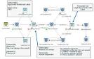
For example, French (1985) has developed a more detailed model of the design process, shown in Figure 10, based on the following activities: analysis of problem; conceptual design; embodiment of schemes; detailing. In the diagram, the circles represent stages reached, or outputs, and the rectangles represent activities, or work in progress.
Engineering Design Methods
Strategies for Product Design
THIRD EDITION
Nigel Cross
The Open University, Mi/ton Keynes, UK
JOHN WILEY & SONS, LTD
Chichester- New York. Weinheim • Brisbane. Singapore. Toronto
for STEP BY STEP GUIDE unigraphics simple tutorial please visit.........
www.unigraphicsimpletutorial.blogspot.com
---or---
Adapting the Generic Product Development Process

The development process described by Exhibits 2-2 and 2-3 is generic, and particular processes will differ in accordance with a firm's unique context. The generic process is most like the process used in a market-pull situation: a firm begins product development with a market opportunity and then uses whatever available technologies are required to satisfY the market need (i.e., the market "pulls" the development decisions). In addition to the marketpull process outlined in Exhibits 2-2 and 2-3, several variants are common and correspond to the following: technology-push products, platform products, process-intensive products,
customized products, high-risk products, quick-build products, and complex systems. Each of these situations is described below. The characteristics of these situations and the resulting deviations from the generic process are summarized in Exhibit 2-4.
Technology-Push Products
In developing technology-push products, the firm begins with a new proprietary technology and looks for an appropriate market in which to apply this technology (that is, the technology "pushes" development). Gore-Tex, an expanded Teflon sheet manufactured by W L. Gore Associates, is a striking example of technology push. The company has developed dozens of products incorporating Gore-Tex, including artificial veins for vascular surgery, insulation for high-performance electric cables, fabric for outerwear, dental floss,
and liners for bagpipe bags.
Many successful technology-push products involve basic materials or basic process technologies. This may be because basic materials and processes are deployed in thousands of applications, and there is therefore a high likelihood that new and unusual characteristics of materials and processes can be matched with an appropriate application.
The generic product development process can be used with minor modifications for technology-push products. The technology-push process begins with the planning phase, in which the given technology is matched with a market opportunity. Once this matching has occurred, the remainder of the generic development process can be followed.
The team includes an assumption in the mission statement that the particular technology will be embodied in the product concepts considered by the team. Although many extremely successful products have arisen from technology-push development, this approach can be perilous. The product is unlikely to succeed unless (1) the assumed technology offers a clear competitive advantage in meeting customer needs, and (2) suitable alternative technologies are unavailable or very difficult for competitors to utilize. Project risk can possibly be minimized by simultaneously considering the merit of a broader set of concepts which do not necessarily incorporate the new technology. In this way the team verifies that the product concept embodying the new technology is superior to the alternatives.
References and Bibliography
Many current resources are available on the Internet via www.ulrich-eppinger.net
Stage-gate product development processes have been dominant in manufacturing firms for the past 30 years. Cooper describes the modem stage-gate process and many of its enabling practices.
Cooper, Robert G., Winning at New Products: Accelerating the Process from Idea to Launch, third edition, Perseus Books, Cambridge, MA, 2001.
for STEP BY STEP GUIDE autocad simple tutorial please visit.........
www.autocadsimpletutorial.blogspot.com
---or---
Learning to Design

An appropriate use of the 'solution-focused' approach to design is something that seems to develop with experience. Experienced designers are able to draw on their knowledge of previous exemplars in their field of design, and they also seem to have learned the value of rapid problem-exploration through solutionconjecture. In comparison, novice designers can often become bogged down in attempts to understand the problem before they start generating solutions. For them, gathering data about the
problem is sometimes just a substitute activity for actually doing any design work.
However, novice designers are also frequently found to become fixated on particular solution concepts. Early solution concepts are often found to be less than satisfactory, as problem exploration continues. Novice designers (and sometimes more experienced ones) can be loath to discard the concept and return to a search for a better alternative. Instead, they try laboriously to design-out the imperfections in the concept, producing slight improvements until something workable but perhaps far from ideal is attained. Sometimes it can be much more productive to start afresh with a new design concept.
Another difference between novices and experts is that novices will often pursue a depth-first approach to a problem: sequentially identifying and exploring sub-solutions in depth, and amassing a number of partial sub-solutions that then somehow have to be amalgamated and reconciled, in a bottom-up process. Experts
usually pursue predominantly breadth-first and top-down strategies, as recorded in the example of the expert designer's decision tree in Figure 6 (Chapter 1). Experienced designers, like any skilled professionals, can make designing seem easy and intuitive. Because skilled design in practice therefore often appears to proceed in a rather ad hoc and unsystematic way, some people claim that learning a systematic process does not actually help student designers. However, a study by Radcliffe and Lee (1989) did show that a systematic
approach can be helpful to students. They found that the use of more efficient design processes (following closer to an ideal sequence) correlated positively with both the quantity and the quality of the students' design results. Other studies have tended to confirm this.
From studies of a number of engineering designers, of varying degrees of experience and with varying exposures to education in systematic design processes, Fricke (1996) found that designers following a 'flexible-methodical procedure' tended to produce good solutions. These designers worked reasonably efficiently and followed a fairly logical procedure, whether or not they had been educated in a systematic approach. In comparison, designers either with a too-rigid adherence to a systematic procedure (behaving 'unreasonably' methodically), or with very unsystematic approaches, produced mediocre or poor design solutions.
Successful designers (ones producing better quality solutions) tended to be those who:
• clarified requirements, by asking sets of related questions which focused on the problem structure
• actively searched for information, and critically checked given requirements
• summarised information on the problem formulation into requirements and partially prioritised them
• did not suppress first solution ideas; they held on to them, but returned to clarifying the problem rather than pursuing initial solution concepts in depth
• detached themselves during conceptual design stages from fixation on early solution concepts
• produced variants but limited the production and kept an overview by periodically assessing and evaluating in order to reduce the number of possible variants.
The key to successful design therefore seems to be the effective management of the dual exploration of both the 'problem space' and the 'solution space'.
Designing is a form of skilled behaviour. Learning any skill usually relies on controlled practice and the development of techniques. The performance of a skilled practitioner appears to flow seamlessly, adapting the performance to the circumstances without faltering. However, learning is not the same as performing,
and underneath skilled performance lies mastery of technique and procedure.
Engineering Design Methods
Strategies for Product Design
THIRD EDITION
Nigel Cross
The Open University, Mi/ton Keynes, UK
JOHN WILEY & SONS, LTD
Chichester- New York. Weinheim • Brisbane. Singapore. Toronto
Concept Development: The Front-End Process
Because the concept development phase of the development process demands perhaps more coordination among functions than any other, many of the integrative development methods presented in this book are concentrated here. In this section we expand the concept development phase into what we call the front-end process. The front-end process generally contains many interrelated activities, ordered roughly as shown in Exhibit 2-3. Rarely does the entire process proceed in purely sequential fashion, completing each activity before beginning the next. In practice, the front-end activities may be overlapped
in time and iteration is often necessary. The dashed arrows in Exhibit 2-3 reflect the uncertain nature of progress in product development. At almost any stage, new information may become available or results learned which can cause the team to step back to repeat an earlier activity before proceeding. This repetition of nominally complete activities is known as development iteration.
The concept development process includes the following activities:
• Identifying customer needs:
The goal of this activity is to understand customers' needs and to effectively communicate them to the development team. The output of this step is a set of carefully constructed customer need statements, organized in a hierarchical list, with importance weightings for many or all of the needs. A method for this activity is presented in Chapter 4, Identifying Customer Needs.
• Establishing target specifications:
Specifications provide a precise description of what a product has to do. They are the translation of the customer needs into technical terms. Targets for the specifications are set early in the process and represent the hopes of the development team. Later these specifications are refined to be consistent with the constraints imposed by the team's choice of a product concept. The output of this
stage is a list of target specifications. Each specification consists of a metric, and marginal and ideal values for that metric. A method for the specification activity is given in Chapter 5, Product Specifications.
• Concept generation:
The goal of concept generation is to thoroughly explore the space of product concepts that may address the customer needs. Concept generation includes a mix of external search, creative problem solving within the team, and systematic exploration of the various solution fragments the team generates. The result of this activity is usually a set of 10 to 20 concepts, each typically represented by a sketch and brief descriptive text. Chapter 6, Concept Generation, describes this activity in detail.
• Concept selection:
Concept selection is the activity in which various product concepts
are analyzed and sequentially eliminated to identify the most promising concept(s).
The process usually requires several iterations and may initiate additional concept generation
and refinement. A method for this activity is described in Chapter 7, Concept
Selection.
• Concept testing: One or more concepts are then tested to verify that the customer needs have been met, assess the market potential of the product, and identify any shortcomings which must be remedied during further development. If the customer response is poor, the development project may be terminated or some earlier activities may be repeated as necessary. Chapter 8, Concept Testing, explains a method for this
activity.
• Setting final specifications:
The target specifications set earlier in the process are revisited after a concept has been selected and tested. At this point, the team must commit to specific values of the metrics reflecting the constraints inherent in the product concept, limitations identified through technical modeling, and trade-offs between cost and performance.Chapter 5, Product Specifications, explains the details of this activity.
• Project planning:
In this final activity of concept development, the team creates a detailed development schedule, devises a strategy to minimize development time, and identifies the resources required to complete the project. The major results of the front-end activities can be usefully captured in a contract book which contains the
mission statement, the customer needs, the details of the selected concept, the product specifications, the economic analysis of the product, the development schedule, the project staffing, and the budget. The contract book serves to document the agreement (contract) between the team and the senior management of the enterprise. A project planning method is presented in Chapter 16, Managing Projects.
• Economic analysis:
The team, often with the support of a financial analyst, builds an economic model for the new product. This model is used to justify continuation of the overall development program and to resolve specific trade-offs among, for example, development costs and manufacturing costs. Economic analysis is shown as one of the
ongoing activities in the concept development phase. An early economic analysis will almost always be performed before the project even begins, and this analysis is updated as more information becomes available. A method for this activity is presented in Chapter 15, Product Development Economics.
• Benchmarking of competitive products:
An understanding of competitive products is critical to successful positioning of a new product and can provide a rich source of ideas for the product and production process design. Competitive benchmarking is performed in support of many of the front-end activities. Various aspects of competitive benchmarking are presented in Chapters 4-8.
• Modeling and prototyping:
Every stage of the concept development process involves various forms of models and prototypes. These may include, among others: early "proof-of-concept" models, which help the development team to demonstrate feasibility; "form-only" models, which can be shown to customers to evaluate ergonomics and style; spreadsheet models of technical trade-offs; and experimental test models, which can be used to set design parameters for robust performance.
References and Bibliography
Many current resources are available on the Internet via
www.ulrich-eppinger.net
Stage-gate product development processes have been dominant in manufacturing firms
for the past 30 years. Cooper describes the modem stage-gate process and many of its
enabling practices.
Cooper, Robert G., Winning at New Products: Accelerating the Process from Idea to
Launch, third edition, Perseus Books, Cambridge, MA, 2001.
How Designers Think

In an experimental research study, Lawson (1984) compared the ways in which designers (in this case architects) and scientists solved the same problem. The scientists tended to use a strategy of systematically trying to understand the problem, in order to look for underlying rules which would enable them to generate an optimum solution. In contrast, the designers tended to make initial explorations and then suggest a variety of possible solutions until they found one that was good, or at least satisfactory.
The evidence from the experiments suggested that scientists problem-solve by analysis, whereas designers problem-solve by synthesis; scientists use 'problem-focused strategies' and designers use 'solution-focused strategies'.
Some other studies have also suggested that designers tend to use conjectures about solution concepts as the means of developing their understanding of the problem. Darke (1984) found that designers impose a primary generator onto the problem, in order to narrow the search space and generate early solution concepts.
This primary generator is usually based on a tightly-restricted set of constraints or solution possibilities derived from the design problem. Since 'the problem' cannot be fully understood in isolation from consideration of 'the solution', it is natural that solution conjectures should be used as a means of helping to explore and understand the problem formulation. Making sketches of solution concepts is one way that helps the designer to identify their consequences, and to keep the problem exploration going, in what Sch6n (1983) called the 'reflective conversation with the situation' that is characteristic of design thinking.
Drawing and sketching have been used in design for a long time, certainly since long before the Renaissance, but the period since that time has seen a massive growth in the use of drawings, as designed objects have become more complex and more novel. Many of Leonardo da Vinci's drawings of machines and inventions
from the Renaissance period show one of the key aspects of design drawings, in terms of their purpose of communicating to someone else how a new product should be built, and also how it should work. Some of Leonardo's design drawings also show how a drawing can be not only a communication aid, but also a thinking and reasoning aid. For example, Leonardo's sketches for the design of fortifications (Figure 7) show how he used sight-lines and missile trajectories as lines to set up the design of the fortifications, and how his design thinking was assisted by drawing. In such drawings we see how the sketch can help the designer to consider many aspects at once; we see plans, elevations, details, trajectory lines, all being drawn together and thus all being thought about, reasoned about, all together.
Half a millenium later, we still see designers using essentially similar types of sketch to aid their design thinking. The early concept sketches for a house design by the contemporary architect Charles Moore (Figure 8) show similar kinds of representations as those used by Leonardo: plan, elevation and section all being
considered together with considerations of structure and calculations of dimensions and areas.
What might we learn about the nature of design thinking from looking at examples of what designers sketch? One thing that seems to appear is that sketches enable designers to handle different levels of abstraction simultaneously. Clearly this is something important in the design process. We see that designers think about the overall concept and at the same time think about detailed aspects of the implementation of that concept. Obviously not all of the detailed aspects are considered early on, because if they could do that, designers could go straight to the final set of detailed drawings. So they use the concept sketch to identify and then to reflect upon critical details, particular details that they realise might hinder or somehow significantly influence the final implementation of the complete design. This implies that, although there is a hierarchical structure of decisions, from overallconcept to details, designing is not a strictly hierarchical process; in the early stages of design, the designer moves freely between different levels of detail.
The identification of critical details is part of a more general facility that sketches provide, which is that they enable identification and recall of relevant knowledge. As the architect Richard MacCormac has said about designing, 'What you need to know about the problem only becomes apparent as you're trying to solve it.' There is a massive amount of information that may be relevant, not only to all the possible solutions for a
design problem, but simply to any possible solution. Any possible solution in itself creates the unique circumstances in which these large bodies of information interact, probably in unique ways for any one possible solution. So these large amounts of information and knowledge need to be brought into play in a selective way, being selected only when they become relevant, as the designer considers the implications of the solution concept as it develops.
Because the design problem is itself ill-defined and ill-structured,
a key feature of design sketches is that they assist problem structuring through the making of solution attempts. Sketches incorporate not only drawings of tentative solution concepts but also numbers, symbols and text, as the designer relates what he knows of the design problem to what is emerging as a solution. Sketching enables exploration of the problem space and the solution space to proceed together, assisting the designer to converge on a matching problem-solution pair. Problem and solution co-evolve in the design process.
Designers' use of sketches therefore gives us some considerable insight into the nature of design thinking and the resolution of design problems. These problems cannot be stated sufficiently explicitly such that solutions can be derived directly from them. The designer has to take the initiative in finding a problem starting point and suggesting tentative solution areas. Problem and solution are then both developed in parallel, sometimes leading to a creative redefinition of the problem, or to a solution that lies outside the boundaries of what was previously assumed to be possible.
Solution-focused strategies are therefore perhaps the best way of tackling design problems, which are by nature ill-defined. In order to cope with the uncertainty of ill-defined problems, the designer has to have the self-confidence to define, redefine and change the problem as given, in the light of solutions that emerge
in the very process of designing. People who prefer the certainty of structured well-defined problems will never appreciate thedelight of being a designer!
Engineering Design Methods
Strategies for Product Design
THIRD EDITION
Nigel Cross
The Open University, Mi/ton Keynes, UK
JOHN WILEY & SONS, LTD
Chichester- New York. Weinheim • Brisbane. Singapore. Toronto


