Thread Cutting operation

In a thread cutting operation the first step is to remove the excess material from the work piece to make its diameter equal to the major diameter of the screw thread. Change gears of correct size are then fitted to the end of the bed between the spindle and the lead screw. The shape or form of the thread depend s on the shape of the cutting tool to be used. In a metric thread, the included angle of the cutting edge should be ground exactly 60o. The top of the tool nose should be set at the same height as the centre of the work piece. A thread tool gauge is usually used against the turned surface to check the cutting tool so that each face of the tool may be equally inclined to the center line of the work piece.
The speed of the spindle is reduced by one half to one-fourth of the speed required for turning according to the type of the material being machined, and the half-nut is then engaged. The depth of cut which usually varies from 0.05 to 0.2 mm is applied by advancing the tool perpendicular at to the axis of the work or at an angle equal to one-half of the angle of the thread, and 30o in the case of metric thread, by swiveling the compound rest.


  • READ MORE.......


  • fr. NTTF ( NETTUR TECHNICAL TRAINING FOUNDATION)


    Recommended Design for Molded-in Threads

    Molded-in threads can be designed into parts made of engineering thermoplastic
    resins. Threads always should have radiused roots and should not have feather
    edges – to avoid stress concentrations.
    Figure 35 shows examples of good design for molded-in external and internal threads. For additional information on molded-in threads, see page 105. Threads also form undercuts and should be treated as such when the part is being removed from the mold i.e., by provision of unscrewing mechanisms, collapsible cores, etc. Every effort should be made to locate external
    threads on the parting line of the mold where economics and mold reliability are
    most favorable.


  • READ MORE.......


  • Product and Mold Design


    Dimensioning principles

    A drawing should provide a complete specification of  the component to ensure that the design intent can be met at all stages of manufacture. Dimensions specifying features of size, position, location, geometric control and surface texture must be defined and appear on the drawing once only. It should not be necessary for the craftsman either to scale the drawing or to deduce dimensions by the subtraction or addition of other dimensions. Double dimensioning is also not acceptable.

    Theoretically any component can be analysed and divided into a number of standard common geometrical shapes such as cubes, prisms, cylinders, parts of cones, etc. The circular hole in Fig. 14.1 can be considered as a cylinder through the plate. Dimensioning a component is the means of specifying the design intent in the manufacture and verification of the finished part.

    A solid block with a circular hole in it is shown in Fig. 14.1 and to establish the exact shape of the item we require to know the dimensions which govern its length, height and thickness, also the diameter and depth of the hole and its position in relation to the surface of the block. The axis of the hole is shown at the intersection of two centre lines positioned from the left hand side and the bottom of the block and these two surfaces have been taken as datums. The length and height have also been measured from these surfaces separately and this is a very important point as errors may become cumulative and this is discussed later in the chapter.

    Dimensioning therefore, should be undertaken with a view to defining the shape or form and overall size
    of the component carefully, also the sizes and positions of the various features, such as holes, counterbores,
    tappings, etc., from the necessary datum planes or axes.
    The completed engineering drawing should also include sufficient information for the manufacture of the part and this involves the addition of notes regarding the materials used, tolerances of size, limits and fits, surface finishes, the number of parts required and any further comments which result from a consideration of the use to which the completed component will be put. For example, the part could be used in sub-assembly
    and notes would then make reference to associated drawings or general assemblies.

    British Standard 8888 covers all the ISO rules applicable to dimensioning and, if these are adhered to, it is reasonably easy to produce a drawing to a good professional standard.
    1 Dimension and projection lines are narrow continuous lines 0.35 mm thick, if possible, clearly placed outside the outline of the drawing. As previously mentioned, the drawing outline is depicted with wide lines of 0.7 mm thick. The drawing outline will then be clearly defined and in contrast with the dimensioning system.
    2 The projection lines should not touch the drawing but a small gap should be left, about 2 to 3 mm, depending on the size of the drawing. The projection lines should then continue for the same distance past the dimension line.
    3 Arrowheads should be approximately triangular, must be of uniform size and shape and in every case touch the dimension line to which they refer. Arrowheads drawn manually should be filled in. Arrowheads drawn by machine need not be filled in.
    4 Bearing in mind the size of the actual dimensions and the fact that there may be two numbers together
    where limits of size are quoted, then adequate space must be left between rows of dimensions and a
    spacing of about 12 mm is recommended.
    5 Centre lines must never be used as dimension lines but must be left clear and distinct. They can be extended, however, when used in the role of projection lines.
    6 Dimensions are quoted in millimetres to the minimum number of significant figures. For example, 19 and not 19.0. In the case of a decimal dimension, always use a nought before the decimal marker, which might not be noticed on a drawing print that has poor line definition. We write 0,4 and not .4. It should be stated here that on metric drawings the decimal marker is a comma positioned on the base line between the figures, for example, 5,2 but never 5·2 with a decimal point midway.
    7 To enable dimensions to be read clearly, figures are placed so that they can be read from the bottom of the drawing, or by turning the drawing in a clockwise direction, so that they can be read from the right hand side.
    8 Leader lines are used to indicate where specific indications apply. The leader line to the hole is directed towards the centre point but terminates at the circumference in an arrow. A leader line for a part number terminates in a dot within the outline of the component. The gauge plate here is assumed to be part number six of a set of inspection gauges.


  • READ MORE.......


  • Manual of
    Engineering Drawing
    Second edition
    Colin H Simmons
    I.Eng, FIED, Mem ASME.
    Engineering Standards Consultant
    Member of BS. & ISO Committees dealing with
    Technical Product Documentation specifications
    Formerly Standards Engineer, Lucas CAV.
    Dennis E Maguire
    CEng. MIMechE, Mem ASME, R.Eng.Des, MIED
    Design Consultant
    Formerly Senior Lecturer, Mechanical and
    Production Engineering Department, Southall College
    of Technology
    City & Guilds International Chief Examiner in
    Engineering Drawing


    ECCENTRIC TURNING, CHAMFERING, THREAD CUTTING LATHE

    If a cylindrical work piece has two separate axis of rotation one being out of centre to the other, the work piece is termed eccentric and turning of different surfaces of the wok piece is known as eccentric turning. The shaft is first mounted on its true centre and the part forming the journal is turned. The job is then remounted on the offset centre and the eccentric surfaces are machined.

    CHAMFERING
    Chamfering is the operation of beveling the extreme end of a work piece this done to remove the burrs, to protect the end of the work piece from being damaged and to have a better look. The operation may be preformed after knurling, rough turning, boring, drilling or thread cutting. Chamfering is an essential operation after thread cutting so that the nut may pass freely on the threaded work piece.

    THREAD CUTTING:
    Thread cutting is the most important operation performed in lathe.
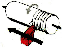
    The principle of thread cutting is to produce a helical groove on a cylindrical or conical surface by feeding the tool longitudinally when job is revolved between centers or by a chuck. The longitudinal feed should be equal to the pitch of thread to be cut per revolution of the work piece. The lead screw of the lathe, through which the saddle receives its traversing motion, has a definite pitch. A definite ratio between the longitudinal feed and rotation of the head stock spindle should therefore be found out so that the relative speeds of rotation of the work and the lead screw will result in the cutting of a screw of the desired pitch. This is affected by change gears arranged between the spindle and lead screw or by the change gear mechanism or feed box used in a modern lathe where it provides a wider range of feed and the speed ratio can be easily and quickly changed.


  • READ MORE.......


  • fr. NTTF ( NETTUR TECHNICAL TRAINING FOUNDATION)


    Labels

    2d (1) 3D (1) ABG (1) agen JNE (1) almari (1) Alufoil (1) Aluminum Foil (1) anilox roll (1) apartemen (1) Atom (1) autocad (1) backdrop logo (1) bagian dalam (1) bangunan (1) batu alam (1) berkualitas (1) bermutu (1) berpengalaman (1) bertingkat (1) birdview (1) black and white (1) botol plastik (1) cafe (1) classic (1) coklat (1) cold rolled sheet (1) Computer To Plate (1) Consumer Understanding (1) control movement (1) counter (1) CTP (1) denah berwarna (1) denah kantor (1) desain (1) desain cuci mobil (1) desain kamar (1) desain produk (1) design (1) Design and Function (1) design meja (1) Design restaurant (1) design rumah (1) di daerah (1) dinding bata (1) dining (1) Duromer (1) Electrons (1) etnik (1) factors (1) flexo packaging (1) flexo printing (1) food (1) furniture (1) gallus (1) gambar (1) gaya modern (1) gloss (1) grc kotak (1) Halftone (1) hanya 550 ribu (1) harga murah (1) hasil cepat (1) hotel (1) industrial (1) injection (1) Injection Mold (1) ink (1) inovatif (1) install (1) interior (1) interior rumah (1) jasa gambar rumah (1) jasa 3d (1) jasa arsitek (1) jasa desain (1) jasa desain 3d (1) jasa design (1) jasa designer (1) jasa gambar (1) kamar tidur (1) kamar tidur anak (1) kampus (1) karaoke (1) kawasan (1) kawasan industri (1) kemasan (1) kerja di rumah (1) kitchen set (1) kontemporer (1) kosan (1) kost (1) krem (1) laci (1) lamination (1) lithography (1) living room (1) livingroom (1) lounge (1) Luscher MultiDX (1) masterplan (1) matt (1) meja kerja (1) metalworking (1) mewah (1) minimalis (1) minimalist (1) modern (1) mold (1) molding (1) Monomer (1) murah (1) murah. (1) Neutron (1) nuansa remaja (1) offset (1) online design (1) open ceiling (1) outdoor (1) overprint (1) pabrik (1) pantai (1) pencahayaan (1) perumahan (1) pesan desain (1) pesan desain toko (1) plug (1) Polimer (1) Polyaddition (1) Polycondensation (1) Polymerization (1) Polystyrene (1) printing ink (1) Product Creation (1) product function (1) produk katalog (1) Protons (1) Raster Image Processor (1) register (1) rendering (1) resepsionis (1) responsibility (1) resto industrial (1) RIP (1) Rotary (1) ruang kantor (1) ruang keluarga (1) ruang kerja (1) ruang tamu (1) ruang tunggu (1) ruko (1) rumah (1) rumah hook (1) rumah susun (1) rumah tropis (1) scandinavian (1) screen printing (1) sederhana (1) sempoa (1) setup (1) simple sederhana (1) specifications (1) spring (1) steel (1) Struktur Plastik (1) suspension (1) sweet home (1) taman (1) tampak (1) tampak rumah (1) Technological Change (1) terbaru (1) termurah (1) toko aksesoris (1) toko asesoris (1) trapping (1) two cavity (1) unscrewing (1) use (1) uv varnish (1) via online (1) website (1)