State of the Art of Design Techniques for Non-Steady-State Metal Forming Processes

Basic Design Techniques
The forging problem can be summarized as to find the best process design, which makes it possible to form the required part. We do not consider the preliminary problem of dressing. We assume that the
forged part has already been designed out of the shape of the final part, which will often be obtained after machining. The problem is just to design a deformation path for the material in order to obtain a prescribed shape with satisfactory properties and for the lower cost. Of course, the deformation paths are not unique, and that can include several forging  operations. So the problem is to find the best shapes of the preforming tools, the best forming temperatures (both the initial temperature of the billet and the temperature of the dies), the best forging velocities, the best lubricant and lubrication conditions, etc.
The optimality conditions regard several parameters which may depend on the process itself. However,
most of the time, the optimal forging design has to obtain the right final part without major defects such as folds, to minimize the number of operations, to minimize the size of the initial billet, to reduce the maximum forging force during the operations, and so on.
This is a complex design problem as often the material flow is three-dimensional and difficult to foresee. It is not possible to simplify it into a less complex problem which could be more easily studied. In fact, in this area, there is a deep lack of simple mathematical models. Just a few problems can be analytically solved, such as the upsetting of a cylinder (or a bar) between flat dies without friction. Although it provides some interesting tendencies, it is far too simple to be useful for the design of a close-die forging process. So, the industrial practice was mainly based on thumb rules and empirical knowledge which have been obtained either by actual experiences, by reduced scale or simulation experiments, or by more complex mathematical models [51, 2].
Some approximated models and methods have been developed, for instance by Chamouard [11], in order to predict the filling of the forging dies and the forging force. Unfortunately, they are not easy to use. In order to bring them within the reach of these persons, recently, the Chamouard’s approach has been incorporated into computer software [56]. However, according to the present computer performances and the restricting hypothesis of such models, this is probably not the most efficient and modern way to simulate the process, as we shall see.
As a matter of fact, all the proposed methods are restricted to two-dimensional (axisymmetrical or plane strain approximation) problems. For complex three-dimensional flows, the 3D problem has first to be decomposed into several 2D plane strain problems (see Fig. 5.1), which is both not easy and not always possible.


  • READ MORE.......


  • COMPUTER-AIDED DESIGN,
    ENGINEERING, AND MANUFACTURING
    Systems Techniques And Applications
    VOLUME
    V I
    Editor
    CORNELIUS LEONDES
    Boca Raton London New York Washington, D.C.
    CRC Press
    MANUFACTURING
    SYSTEMS PROCESSES


    Step formation and release of products in blow Blow Molding

    Mold is opened, after a long-parison which flows through the side pieces, mold will close, followed by movement of the blades are cut off above the parison mold. After the parison mold stuck on the move, which was originally under the tip of the die head is now under blowpin, Then blowpin down to blow the parison to expand the shape of the cavity.
    At the top of the mold are part of a hardened steel, serves as the foundation adjacent to the cutting of the parison excess of the mold.
    The foundation is called the striker plate cutting, cutter was called the outing blowpin end of the sleeve is attached.

    Product formation steps and expenditures.
    1.Mold catch parison, the knife cut off the excess parison upper mold, then mold moves downward move the position of blowpin.
    2.Blowpin move down to blow the parison into a product, which is then followed by cooling the product in the mold.
    3.The process of cooling, the mold opens and moves towards the bottom to catch the parison die head again. It is equivalent blowpin move, which goes along with the product because the mouth(which is due to shrinkage after cooling) blowpin gripping end.
    4.Blowpin rose steadily up to the mouth blowpin held back by the nest, regardless of the end blowpin and fall. Meanwhile parison mold was arrested and will move down blowpin next to the blowing process.


  • READ MORE.......


  • Thread Cutting operation

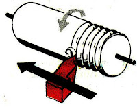
    In a thread cutting operation the first step is to remove the excess material from the work piece to make its diameter equal to the major diameter of the screw thread. Change gears of correct size are then fitted to the end of the bed between the spindle and the lead screw. The shape or form of the thread depend s on the shape of the cutting tool to be used. In a metric thread, the included angle of the cutting edge should be ground exactly 60o. The top of the tool nose should be set at the same height as the centre of the work piece. A thread tool gauge is usually used against the turned surface to check the cutting tool so that each face of the tool may be equally inclined to the center line of the work piece.
    The speed of the spindle is reduced by one half to one-fourth of the speed required for turning according to the type of the material being machined, and the half-nut is then engaged. The depth of cut which usually varies from 0.05 to 0.2 mm is applied by advancing the tool perpendicular at to the axis of the work or at an angle equal to one-half of the angle of the thread, and 30o in the case of metric thread, by swiveling the compound rest.


  • READ MORE.......


  • fr. NTTF ( NETTUR TECHNICAL TRAINING FOUNDATION)


    Recommended Design for Molded-in Threads

    Molded-in threads can be designed into parts made of engineering thermoplastic
    resins. Threads always should have radiused roots and should not have feather
    edges – to avoid stress concentrations.
    Figure 35 shows examples of good design for molded-in external and internal threads. For additional information on molded-in threads, see page 105. Threads also form undercuts and should be treated as such when the part is being removed from the mold i.e., by provision of unscrewing mechanisms, collapsible cores, etc. Every effort should be made to locate external
    threads on the parting line of the mold where economics and mold reliability are
    most favorable.


  • READ MORE.......


  • Product and Mold Design