Forging Simulation

According to the difficulties which have just been presented, the design problem often results in trial and error. It is both time and money  consuming, as the shapes of the dies are complex, difficult, and expensive to produce. In order to lower these costs, several simulation strategies have been developed to replace the actual trials. Easy to form model materials such as lead, plasticine [52], and wax [64] can be substituted to the current metal, making it possible to reduce the forming force. These materials, and more particularly plasticine and wax which are more widely used today, exhibit nearly the same behavior as the metal under hot isothermal conditions. One of the main restriction of this approach is the temperature dependency of the model materials, which is quite different from the behavior of the metal.

However, for most of the processes, the forging is so fast that the heat exchanges with the dies is small and that the heat generated by the material deformation is not enough to significantly modify the material flow. Thus, this technique provides an easy way to study the material flow, to predict the major defects such as folds [42] and insufficient pressure in the die details, and to estimate the forging force. Moreover, it is possible to study the material deformation and the fibering by mixing model materials of several colors. With some mechanical models, the total strain can be computed out of these pieces of information [52]. By mixing model materials with different properties, or by adding some other components, the behavior of the model material can be slightly adjusted to the behavior of the studied metal. As often for metal forming processes, the friction phenomenon is difficult to simulate. However, some kind of model materials for the lubricants can be proposed.

The main shortcoming of this simulation approach is that although the dies can be produced into a less expensive material and without heat treatment, they are as complex as the actual process, which requires significant time and energy to produce them. Moreover, as has been mentioned earlier, the thermal effects cannot be taken into account.

Nowadays, the numerical simulation provides much faster results as the toolings are only virtually designed. Moreover, these results are more accurate and more varied, such as the flow at different times of the process, the velocity field, the strain, the strain rates, the stresses, the temperature, the tool wear, and the tool deformation. Several softwares have been marketed, such as the well spread FORGE2 and DEFORM2D (initially called ALPID), [47] for axisymmetrical and plane strain problems.
They are actual tools for designers and their industrial use is ever increasing. Indeed, they make it easy to quickly find the main shortcomings of the studied design, and then to test several modifications to improve it. For expensive safety parts, or for very large single parts, they also provide a quality insurance as they give an estimation of the mechanical characteristics of the part which should otherwise be obtained by destructive testing. Regarding the true three-dimensional problems, automatic remeshing difficulties, as well as  computational time and memory requirements, have long hindered the industrial use of these softwares. 

Nowadays, both the software and hardware progresses have made these computations possible. They are used in forging companies, for instance to understand the development of a fold and test whether a new preform design can remove it [22]. The tool shape discretization required for the numerical simulation, often a finite element mesh of the tool surface by triangles, can almost directly be obtained from the CAD design. It reduces to rather insignificant times the specific numerical design required by the finite element simulation. FORGE3 and DEFORM3D [66] are such available softwares


  • READ MORE.......


  • COMPUTER-AIDED DESIGN,
    ENGINEERING, AND MANUFACTURING
    Systems Techniques And Applications
    VOLUME V I
    Editor
    CORNELIUS LEONDES
    Boca Raton London New York Washington, D.C.
    CRC Press
    MANUFACTURING
    SYSTEMS PROCESSES


    Facing, KNURLING, FILING

    Facing
    Facing is the operation of machining the ends of a piece of work to produce a flat surface square with the axis. This is also used to cut the work to the required length. The operation involves feeding the tool perpendicular to the axis of rotation of the work piece.

    KNURLING
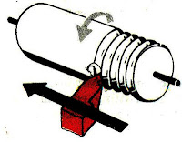
    Knurling is the process of embossing a diamond shaped pattern on the surface of a work piece. The purpose of knurling is to provide an effective gripping surface on a work piece to prevent it from slipping when operated by hand. The tool is held rigidly on the tool post and the rollers are pressed against the revolving work piece to squeeze the metal against the multiple cutting edges, producing depressions in a regular pattern on the surface of the work piece.

    FILING
    Filing is the finishing operation performed after turning. This is done in a lathe to remove burrs, shape corners, and feed marks on a work piece and also to bring it to the size by removing very small amount of metal. The speed is usually twice that of turning. The file should b slowly moved forward so that the work may pass 2 to 3 revolutions during the cutting stroke. During the return stroke the pressure is relived but an end wise feeding movement is given, overlapping the previous cut.


  • READ MORE.......


  • fr. NTTF ( NETTUR TECHNICAL TRAINING FOUNDATION)


    ISO tolerance ranges

    Tolerance bands need to be defined which can be related to functional
    performance and manufacturing processes. The ISO has published tolerance ranges to help designers. Examples of these tolerance ranges are shown in Figure 5.4. This table is only a selection from the full table given in ISO 286-2:1988. The full range goes up to IT18 and 3m nominal size. The tolerance ranges are defined by 'IT' ranges as shown in the  diagram from IT1 to IT11. The range given in the ISO standard is significantly more complicated than the extract in Figure 5.4. It should be noted that the range increases as the IT number gets larger and the range increases as the nominal size increases. The latter is fairly logical in
    that one would expect the tolerance range to be larger as the diameter increases because the precision that can be achieved must be relative. The ranges were not chosen out of the blue but empirically derived and based on the fact that the relationship between manufacturing errors and basic size can be approximated by a parabolic function.


  • READ MORE.......


  • Engineering Drawing for Manufacture
    by Brian Griffiths
    · ISBN: 185718033X
    · Publisher: Elsevier Science & Technology Books


    State of the Art of Design Techniques for Non-Steady-State Metal Forming Processes

    Basic Design Techniques
    The forging problem can be summarized as to find the best process design, which makes it possible to form the required part. We do not consider the preliminary problem of dressing. We assume that the
    forged part has already been designed out of the shape of the final part, which will often be obtained after machining. The problem is just to design a deformation path for the material in order to obtain a prescribed shape with satisfactory properties and for the lower cost. Of course, the deformation paths are not unique, and that can include several forging  operations. So the problem is to find the best shapes of the preforming tools, the best forming temperatures (both the initial temperature of the billet and the temperature of the dies), the best forging velocities, the best lubricant and lubrication conditions, etc.
    The optimality conditions regard several parameters which may depend on the process itself. However,
    most of the time, the optimal forging design has to obtain the right final part without major defects such as folds, to minimize the number of operations, to minimize the size of the initial billet, to reduce the maximum forging force during the operations, and so on.
    This is a complex design problem as often the material flow is three-dimensional and difficult to foresee. It is not possible to simplify it into a less complex problem which could be more easily studied. In fact, in this area, there is a deep lack of simple mathematical models. Just a few problems can be analytically solved, such as the upsetting of a cylinder (or a bar) between flat dies without friction. Although it provides some interesting tendencies, it is far too simple to be useful for the design of a close-die forging process. So, the industrial practice was mainly based on thumb rules and empirical knowledge which have been obtained either by actual experiences, by reduced scale or simulation experiments, or by more complex mathematical models [51, 2].
    Some approximated models and methods have been developed, for instance by Chamouard [11], in order to predict the filling of the forging dies and the forging force. Unfortunately, they are not easy to use. In order to bring them within the reach of these persons, recently, the Chamouard’s approach has been incorporated into computer software [56]. However, according to the present computer performances and the restricting hypothesis of such models, this is probably not the most efficient and modern way to simulate the process, as we shall see.
    As a matter of fact, all the proposed methods are restricted to two-dimensional (axisymmetrical or plane strain approximation) problems. For complex three-dimensional flows, the 3D problem has first to be decomposed into several 2D plane strain problems (see Fig. 5.1), which is both not easy and not always possible.


  • READ MORE.......


  • COMPUTER-AIDED DESIGN,
    ENGINEERING, AND MANUFACTURING
    Systems Techniques And Applications
    VOLUME
    V I
    Editor
    CORNELIUS LEONDES
    Boca Raton London New York Washington, D.C.
    CRC Press
    MANUFACTURING
    SYSTEMS PROCESSES


    Step formation and release of products in blow Blow Molding

    Mold is opened, after a long-parison which flows through the side pieces, mold will close, followed by movement of the blades are cut off above the parison mold. After the parison mold stuck on the move, which was originally under the tip of the die head is now under blowpin, Then blowpin down to blow the parison to expand the shape of the cavity.
    At the top of the mold are part of a hardened steel, serves as the foundation adjacent to the cutting of the parison excess of the mold.
    The foundation is called the striker plate cutting, cutter was called the outing blowpin end of the sleeve is attached.

    Product formation steps and expenditures.
    1.Mold catch parison, the knife cut off the excess parison upper mold, then mold moves downward move the position of blowpin.
    2.Blowpin move down to blow the parison into a product, which is then followed by cooling the product in the mold.
    3.The process of cooling, the mold opens and moves towards the bottom to catch the parison die head again. It is equivalent blowpin move, which goes along with the product because the mouth(which is due to shrinkage after cooling) blowpin gripping end.
    4.Blowpin rose steadily up to the mouth blowpin held back by the nest, regardless of the end blowpin and fall. Meanwhile parison mold was arrested and will move down blowpin next to the blowing process.


  • READ MORE.......


  • Thread Cutting operation

    In a thread cutting operation the first step is to remove the excess material from the work piece to make its diameter equal to the major diameter of the screw thread. Change gears of correct size are then fitted to the end of the bed between the spindle and the lead screw. The shape or form of the thread depend s on the shape of the cutting tool to be used. In a metric thread, the included angle of the cutting edge should be ground exactly 60o. The top of the tool nose should be set at the same height as the centre of the work piece. A thread tool gauge is usually used against the turned surface to check the cutting tool so that each face of the tool may be equally inclined to the center line of the work piece.
    The speed of the spindle is reduced by one half to one-fourth of the speed required for turning according to the type of the material being machined, and the half-nut is then engaged. The depth of cut which usually varies from 0.05 to 0.2 mm is applied by advancing the tool perpendicular at to the axis of the work or at an angle equal to one-half of the angle of the thread, and 30o in the case of metric thread, by swiveling the compound rest.


  • READ MORE.......


  • fr. NTTF ( NETTUR TECHNICAL TRAINING FOUNDATION)


    Recommended Design for Molded-in Threads

    Molded-in threads can be designed into parts made of engineering thermoplastic
    resins. Threads always should have radiused roots and should not have feather
    edges – to avoid stress concentrations.
    Figure 35 shows examples of good design for molded-in external and internal threads. For additional information on molded-in threads, see page 105. Threads also form undercuts and should be treated as such when the part is being removed from the mold i.e., by provision of unscrewing mechanisms, collapsible cores, etc. Every effort should be made to locate external
    threads on the parting line of the mold where economics and mold reliability are
    most favorable.


  • READ MORE.......


  • Product and Mold Design


    Dimensioning principles

    A drawing should provide a complete specification of  the component to ensure that the design intent can be met at all stages of manufacture. Dimensions specifying features of size, position, location, geometric control and surface texture must be defined and appear on the drawing once only. It should not be necessary for the craftsman either to scale the drawing or to deduce dimensions by the subtraction or addition of other dimensions. Double dimensioning is also not acceptable.

    Theoretically any component can be analysed and divided into a number of standard common geometrical shapes such as cubes, prisms, cylinders, parts of cones, etc. The circular hole in Fig. 14.1 can be considered as a cylinder through the plate. Dimensioning a component is the means of specifying the design intent in the manufacture and verification of the finished part.

    A solid block with a circular hole in it is shown in Fig. 14.1 and to establish the exact shape of the item we require to know the dimensions which govern its length, height and thickness, also the diameter and depth of the hole and its position in relation to the surface of the block. The axis of the hole is shown at the intersection of two centre lines positioned from the left hand side and the bottom of the block and these two surfaces have been taken as datums. The length and height have also been measured from these surfaces separately and this is a very important point as errors may become cumulative and this is discussed later in the chapter.

    Dimensioning therefore, should be undertaken with a view to defining the shape or form and overall size
    of the component carefully, also the sizes and positions of the various features, such as holes, counterbores,
    tappings, etc., from the necessary datum planes or axes.
    The completed engineering drawing should also include sufficient information for the manufacture of the part and this involves the addition of notes regarding the materials used, tolerances of size, limits and fits, surface finishes, the number of parts required and any further comments which result from a consideration of the use to which the completed component will be put. For example, the part could be used in sub-assembly
    and notes would then make reference to associated drawings or general assemblies.

    British Standard 8888 covers all the ISO rules applicable to dimensioning and, if these are adhered to, it is reasonably easy to produce a drawing to a good professional standard.
    1 Dimension and projection lines are narrow continuous lines 0.35 mm thick, if possible, clearly placed outside the outline of the drawing. As previously mentioned, the drawing outline is depicted with wide lines of 0.7 mm thick. The drawing outline will then be clearly defined and in contrast with the dimensioning system.
    2 The projection lines should not touch the drawing but a small gap should be left, about 2 to 3 mm, depending on the size of the drawing. The projection lines should then continue for the same distance past the dimension line.
    3 Arrowheads should be approximately triangular, must be of uniform size and shape and in every case touch the dimension line to which they refer. Arrowheads drawn manually should be filled in. Arrowheads drawn by machine need not be filled in.
    4 Bearing in mind the size of the actual dimensions and the fact that there may be two numbers together
    where limits of size are quoted, then adequate space must be left between rows of dimensions and a
    spacing of about 12 mm is recommended.
    5 Centre lines must never be used as dimension lines but must be left clear and distinct. They can be extended, however, when used in the role of projection lines.
    6 Dimensions are quoted in millimetres to the minimum number of significant figures. For example, 19 and not 19.0. In the case of a decimal dimension, always use a nought before the decimal marker, which might not be noticed on a drawing print that has poor line definition. We write 0,4 and not .4. It should be stated here that on metric drawings the decimal marker is a comma positioned on the base line between the figures, for example, 5,2 but never 5·2 with a decimal point midway.
    7 To enable dimensions to be read clearly, figures are placed so that they can be read from the bottom of the drawing, or by turning the drawing in a clockwise direction, so that they can be read from the right hand side.
    8 Leader lines are used to indicate where specific indications apply. The leader line to the hole is directed towards the centre point but terminates at the circumference in an arrow. A leader line for a part number terminates in a dot within the outline of the component. The gauge plate here is assumed to be part number six of a set of inspection gauges.


  • READ MORE.......


  • Manual of
    Engineering Drawing
    Second edition
    Colin H Simmons
    I.Eng, FIED, Mem ASME.
    Engineering Standards Consultant
    Member of BS. & ISO Committees dealing with
    Technical Product Documentation specifications
    Formerly Standards Engineer, Lucas CAV.
    Dennis E Maguire
    CEng. MIMechE, Mem ASME, R.Eng.Des, MIED
    Design Consultant
    Formerly Senior Lecturer, Mechanical and
    Production Engineering Department, Southall College
    of Technology
    City & Guilds International Chief Examiner in
    Engineering Drawing


    ECCENTRIC TURNING, CHAMFERING, THREAD CUTTING LATHE

    If a cylindrical work piece has two separate axis of rotation one being out of centre to the other, the work piece is termed eccentric and turning of different surfaces of the wok piece is known as eccentric turning. The shaft is first mounted on its true centre and the part forming the journal is turned. The job is then remounted on the offset centre and the eccentric surfaces are machined.

    CHAMFERING
    Chamfering is the operation of beveling the extreme end of a work piece this done to remove the burrs, to protect the end of the work piece from being damaged and to have a better look. The operation may be preformed after knurling, rough turning, boring, drilling or thread cutting. Chamfering is an essential operation after thread cutting so that the nut may pass freely on the threaded work piece.

    THREAD CUTTING:
    Thread cutting is the most important operation performed in lathe.
    The principle of thread cutting is to produce a helical groove on a cylindrical or conical surface by feeding the tool longitudinally when job is revolved between centers or by a chuck. The longitudinal feed should be equal to the pitch of thread to be cut per revolution of the work piece. The lead screw of the lathe, through which the saddle receives its traversing motion, has a definite pitch. A definite ratio between the longitudinal feed and rotation of the head stock spindle should therefore be found out so that the relative speeds of rotation of the work and the lead screw will result in the cutting of a screw of the desired pitch. This is affected by change gears arranged between the spindle and lead screw or by the change gear mechanism or feed box used in a modern lathe where it provides a wider range of feed and the speed ratio can be easily and quickly changed.


  • READ MORE.......


  • fr. NTTF ( NETTUR TECHNICAL TRAINING FOUNDATION)


    CORNERS Injection moulding

    When the ideas of correct and uniform wall thickness are put into practice the result is a plastics part composed of relatively thin
    surfaces. The way in which these surfaces are joined is equally vital to the quality of a moulded part.
    Walls usually meet at right angles, at the corners of a box for example. Where the box walls meet the base, the angle will generally be slightly more than 90 degrees because of a draft angle on the walls. The easiest way, and the worst, to join the walls is to bring them together with sharp corners inside and out. This causes two problems.
    The first difficulty is that the increase in thickness at the corner breaks the rule of uniform wall thickness. The maximum thickness at a sharp corner is about 1.4
    times the nominal wall thickness. The result is a longer cooling time accompanied by a risk of sink marks and warping due to differential shrinkage.
    The other problem is even more serious.
    Sharp corners concentrate stress and greatly increase the risk of the part failing in service. This is true for all materials and especially so for plastics. Plastics are said to be notch-sensitive because of their marked tendency to break at sharp corners. This happens because the stress concentration at the corner is sufficient to initiate a microscopic crack which spreads right through the wall to cause total failure of the part. Sharp internal corners and notches are the single most common cause of mechanical failure in moulded parts.
    The answer is to radius the internal corner, but what size should the radius be? Most walls approximate to a classical cantilever structure so it is possible to calculate stress concentration factors for a range of wall thicknesses and radii. The resulting graph shows that the stress concentration increases very sharply when the ratio of radius to wall thickness falls below 0.4. So the internal radius (r) should be at least half the wall thickness (t) and preferably be in the range 0.6 to 0.75 times wall thickness.
    If the inner corner is radiussed and the outer corner left sharp, there is still a thick point at the corner. For an internal radius of 0.6t, the maximum thickness increases to about 1.7 times the wall thickness. We can put this right by adding a radius to the outside corner as well. The outside radius should be equal to the inside radius plus the wall thickness. This results in a constant wall thickness


    DESIGNER’S NOTEBOOK
    Avoid sharp internal corners.
    Internal radii should be at least 0.5 and preferably 0.6 to 0.75 times the wall thickness.
    Keep corner wall thickness as close as possible to the nominal wall thickness. Ideally, external radii should be equal to the internal radii plus the wall thickness.


  • READ MORE.......


  • DESIGN GUIDES for PLASTICS
    Clive Maier, Econology Ltd
    pdg
    Plastics Design Group - Plastics Consultancy Network
    British Plastics Federation


    CLASSIFICATION OF DRAWING

    Machine Drawing
    It is pertaining to machine parts or components. It is presented through a number of orthographic views, so that the size and shape of the  component is fully understood. Part drawings and assembly drawings belong to this classification. An example of a machine drawing is given in Fig. 1.1.


    Production Drawing
    A production drawing, also referred to as working drawing, should furnish all the dimensions, limits and special finishing processes such as heat treatment, honing, lapping, surface finish, etc., to guide the craftsman on the shop floor in producing the component. The title should also mention the material used for the product, number of parts required for the assembled unit, etc.
    Since a craftsman will ordinarily make one component at a time, it is advisable to prepare the production drawing of each component on a separate sheet. However, in some cases the drawings of related omponents may be given on the same sheet. Figure 1.2 represents an example of a production drawing.

    Part drawing
    Component or part drawing is a detailed drawing of a component to facilitate its manufacture. All the  principles of orthographic projection and the technique of graphic representation must be followed to communicate the details in a part drawing. A part drawing with production details is rightly called as a production drawing or working drawing.

    Assembly drawing
    A drawing that shows the various parts of a machine in their correct working locations is an assembly drawing (Fig. 1.3). There are several types of such drawings

  • READ MORE.......


  • MACHINE DRAWING
    Dr.K.L.Narayana
    Dr.P.Kannaiah
    K.Venkata Reddy
    www.newagepublisher.com
    NEW AGE INTERNATIONAL (P) LIMITED, PUBLISHER


    Stretching INJECTION BLOW

    These machines are usually used for the manufacture of PET bottles DNG material, where the process of formation of products through the 3 stages of injection, stretching and blowing but DNG certain type of screw can be used also for other materials such as Polypropilene (PP) dng a particular grade.


    PET bottle-making process itself usually there are 2 ways
    1.SINGLE (ONE) STAGE
    -All the process of making preform until it becomes the bottle in one machine
    2.DOUBLE (TWO) STAGE
    -The process of making DNG preform injection machine and then a new engine in DNG stretching BLOW Blow Molding (separate)

    COMPONENTS AND FUNCTIONS OF MOLD ISB
    1.INJECTION cavity preform
    -To make the outside of the preform shape
    2.CORE ROD
    -To make the inside of the preform
    3.LIP cavity
    -To make the mouth of the bottle preform
    4.NECK RING
    -For the manufacture of the preform neck
    5.BLOW SHELL
    -To create the desired product form

    6.HEATING POT (POT CONDITIONING)
    -For conditioning the preform temperature before curl
    7.STRECHING ROD
    -To encourage the concurrent preform blow dng in the process of formation of the desired product.
    8.STRIPPER PLATE
    -To drop a product that has been established
    PART 9.BOTTOM
    -To form the bottom part of the bottle


  • READ MORE.......


  • Epicyclic Gear Trains

    When at least one of the gear axes rotates relative to the frame in addition to the gear's own rotation about its own axes, the train is called a planetary gear train or epicyclic gear train. The term ``epicyclic'' comes from the fact that points on gears with moving axes of rotation describe epicyclic paths. When a generating circle (planet gear) rolls on the outside of another circle, called a directing circle (sun gear), each point on the generating circle describes an epicycloid, as shown in Fig. 2.7.
    Generally, the more planet gears there are, the greater is the torque capacity of the system. For better load balancing, new designs have two sun gears and up to 12 planetary assemblies in one casing.
    In the case of simple and compound gears, it is not difficult to visualize the motion of the gears, and the determination of the speed ratio is relatively easy. In the case of epicyclic gear trains, it is often diffuclt to visualize the motion of the gears. A systematic procedure using the contour method is presented in what follows. The contour method is applied to determine the distribution of velocities for an epicyclic gear train.


  • READ MORE.......


  • Mechanical Engineer's Handbook
    Edited by
    Dan B. Marghitu
    Department of Mechanical Engineering, Auburn University,
    Auburn, Alabama

    Academic Press Series in Engineering
    Series Editor
    J. David Irwin
    Auburn University


    Variations and Extension to the Injection-Molding Process

    Injection Blow Molding. 
    A preform (this looks like a test tube with bottle cap threads) is injection molded in one cavity, removed and then placed into another where it is pressurized with gas to stretch the hot preform into a thinnerwalled
    seamless bottle or container such as a milk bottle or gas tank. This is depicted in Figure 7. This is an extension of injection molding more than a variation.

    Injection Compression/Coining. 
    With this technique the mold is only partially closed during injection. At the appropriate time and with the right amount of plastic in the mold, the clamp is then completely closed, forcing (compressing) the plastic to the shape of the mold cavity. A variation on this is coining.
    The clamp is closed but the mold has components that compress the plastic in the cavity as the plastic cools. Coining is where the cavity volume is changing during the solidification of the plastic. Plastic is injected into the cavity and then the movable platen closes completely, or a mold component moves to compress the
    plastic to compensate for shrinkage or densification.


  • READ MORE.......


  • “Injection Molding” in EPSE 2nd ed., Vol. 8, pp. 102–138, by I. I. Rubin, Robinson Plastic Corp.
    JOHN W. BOZZELLI
    Midland, Michigan

    Members of Design Teams

    The number and type of individuals that comprise a design team is largely determined by the size of the design project. Even though an individual is assigned to a team, all members may not be involved at all times. In a concurrent engineering environment the team members work together to meet the common goal. Typical members of a design team might include:
    I. Product design engineer-responsible for the overall product design.
    2. Product manager-the person who has the ultimate responsibility for a design and its team.
    3. Mechanical engineer-responsible for mechanical and electromechanical product development.
    4. Electrical engineer-responsible for electronic components of the design.
    5. Manufacturing engineer-responsible for the manufacturing processes used to create the product.
    6. Software engineer-responsible for any computer software code needed for a product.
    7. Detailer/drafter-assists the engineers with the 3-D modeling and documentation of the product.
    8. Materials engineer-responsible for the selection of the material hest suited for a product.
    9. Quality control engineer-responsible for meeting the quality guidelines for the product and its
    manufacture.
    10. Industrial designer-responsible for the product's appearance, form. and human factors analysis.
    II. Vendor representatives-responsible for any outsourcing required by the company making the design.


  • READ MORE.......


  • The Engineering Design Process
    Bertoline-Wiebe-Miller: Fundamentals of Graphics Communication,
    The McGraw-Hill Companies, 2001

    Mechanical properties

    Strength
    The nominal yield strength shall be in the range of 235 N/mm2 to 690 N/mm2. The nominal tensile strength shall be in the range of 300 N/mm2 to 1000 N/mm2.

    Ductility
    The elongation after fracture on proportional gauge length shall be at least 15 %, for nominal yield strength not greater than 460 N/mm2; and shall be at least 10 % for nominal yield strength greater than 460 N/mm2.
    The tensile strength to yield strength ratio shall be at least 1.2 based on nominal values, or at least 1.1 based on actual values, for nominal yield strength not greater than 460 N/mm2.
    NOTE Conversion of elongation values measured not based on proportional gauge length is necessary and shall be performed according to BS EN ISO 2566-1.

    Impact toughness
    As a minimum, the product shall be able to absorb at least 27 J of impact energy at 20 °C.
    NOTE Depending on other factors including the thickness and minimum service temperature, the impact toughness should also conform to the appropriate requirements as given in BS 5950-1.

    Through thickness deformation properties
    Where appropriate, through thickness deformation properties shall be specified to guarantee adequate
    deformation capacity perpendicular to the surface to provide ductility and toughness against lamellar tearing.
    NOTE Specification of through thickness deformation properties can be referred to BS EN 10164.


  • READ MORE.......


  • Design Guide on Use of
    Alternative
    Steel
    Materials
    to BS 5950
    a touche design production @ 6743 5450
    BCA Sustainable Construction
    Series – 3
    200 Braddell Road Singapore 579700

    Cold runner

    Expenditures runner of the mold.
    Way of the runner of the mold usually closely related to the type of gate is used. From this emerged a two plate mold design and three-plate mold. Gate Mold type: strip gate, tunnel gate and gate flash,
    if there is no requirement or a specific form of the product, mold will be designed with two plates.

    At the time of mold starts to open, regardless of the sprue runner R for pin carried by runners who have undercut at the edges.Meanwhile, the gate tunnel cavity disconnected from the product because it was interrupted by the lip of the pit gate. At the opening of the next runner mold and product driven by the stripper plate, the runner forcibly detached from the undercut at the end of the  runner-pin, then fell with the product. Here can be seen, that the mold with a tunnel gate will produce a product that has been separated from the runner. Being a product with a strip gate still hung with runnernya, to require additional work to cut the tow runner from the product.


  • READ MORE.......


  • Design tasks

    The design tasks of this particular project were a bit unusual. The contracting utility had already built the reactor and the buildings to house the control room. The control room designers, therefore, had to design a control room for an already existing plant, with consideration of the sensors and actuators that were present. Functional
    information, however, was largely lacking. For example, it would be known from plant drawings that a certain feedwater stream had x number of valves of which some
    were manually controllable. Functionally, however, it would not be known what purpose that feedwater stream served. In many cases, engineers had to infer design purposes from the drawings. For the most part, the plant was `wired already, meaning that sensors and their signals already existed. In particular, the level of automation of plant systems was pre-determined. In addition, the control room itself had to "t within the existing space allotted for the control room, with walls, doors, and basic wiring in fixed locations.


  • READ MORE.......


  • A participant-observer study of ergonomics in engineering design:
    how constraints drive design process
    Catherine M. Burns*,1, Kim J. Vicente
    Cognitive Engineering Laboratory, Department of Mechanical & Industrial Engineering, University of Toronto, Canada
    www.elsevier.com

    Feed gearbox Lathe

    The feed gearbox or quick-change gearbox is fitted directly below the head stock assembly. Power from the lathe spindle is transmitted through gears to the quick-change gearbox. This gear box contains a number of different sizes of gear which provides a means to change the rate of the feed, and the ratio between the revolutions of the head stock spindle and the movement of the carriage for thread cutting by altering the speed of motion of feed rod or lead screw.
    The arrangement which are employed in feed gear boxes to obtain multiple speeds and different rates of feed are:
    1.Sliding gear mechanism
    2.Sliding clutch mechanism
    3.Gear cone and tumbler gear mechanism
    4.Sliding key mechanism
    5.Combination of any two or more of the above

    Feed rod
    The feed rod is a long shaft that has the key way extending from the feed box across and in front of the bed. The power is transmitted from the lathe spindle to the apron gears through a feed rod via large number of gears. The feed rod is used to move the carriage or cross-slide for turning, boring, facing and all other operations except thread cutting.

    Lead screw
    The lead screw is a long threaded shaft used as a master screw, and is brought into operation only when threads have to be cut. In all other times the lead screw is disengaged from the gear box and remains stationary, but this ma be used to provide motion for turning, boring, etc. in lathes that are not equipped with a feed rod.

    Apron Mechanism
    The apron mechanism is used for transforming rotary motion of the feed rod and the lead screw into feed motion of the carriage. The mechanism also ensures that when the half nut is engaged with the lead screw the worm drops down disconnecting the feed motion. This arrangement is called foolproof arrangement and saves the machine from any damage.


  • READ MORE.......


  • fr. NTTF ( NETTUR TECHNICAL TRAINING FOUNDATION)

    RIVETS

    A rivet is a fastener that has a head and a shank and is made of a deformable material.
    It is used to join several parts by placing the shank into holes through the several parts and creating another head by upsetting or deforming the projecting shank.
    During World War II, Rosie the Riveter was a popular cartoon character in the United States. No better image can illustrate the advantages of riveted joints.These are
    1. Low cost
    2. Fast automatic or repetitive assembly
    3. Permanent joints
    4. Usable for joints of unlike materials such as metals and plastics
    5. Wide range of rivet shapes and materials
    6. Large selection of riveting methods, tools, and machines
    Riveted joints, however, are not as strong under tension loading as are bolted joints (see Chap. 22), and the joints may loosen under the action of vibratory tensile or shear forces acting on the members of the joint. Unlike with welded joints, special sealing methods must be used when riveted joints are to resist the leakage of gas or fluids.


  • READ MORE.......


  • Joseph E. Shigley
    Professor Emeritus
    The University of Michigan
    Ann Arbor,Michigan
    Source: STANDARD HANDBOOK OF MACHINE DESIGN
    Downloaded from Digital Engineering Library @ McGraw-Hill (www.digitalengineeringlibrary.com)
    Copyright © 2004 The McGraw-Hill Companies. All rights reserved.
    Any use is subject to the Terms of Use as given at the website.

    Tunnel gate and Runner

    Tunnel gate is usually conical beheaded, overhanging one side sloping cavity or product. Gate hole diameter d must Consider the weight of the product, the condition of cross-section with long-bends and runners. As a measure taken beginning 0.8 mm to around 10 grams of product weight. After the trial if showed signs are too small gate, gate be enlarged as needed.

    Runner is a conduit between the nozzle on the end of the barrel with a cavity in the mold. Melting plastic in the room at the end of the barrel which is the injection, flow through the hole nozzle, sprue holes, conduit or runner, gate and finally enter into the cavity, because it will be a product. Moderate plastic that fills the channels along the runner and sprue, is a waste that must be removed from the mold along with the current product expenditures.
    Because it is a waste, then the mold with a cavity much, cavity layout and conditions runner distribution must be considered, in order to get the runner channels as short as possible. With a short runner channel, cross-sectional runner can be made smaller, so the weight of materials that become waste (know by heart) would be small, given the weight - the channel cross section x length x channel density.
    Condition of cross section and channel length of the sprue runner each cavity are cultivated together, so that received an injection pressure of each cavity so that the filling of each same acvity balanced.


  • READ MORE.......

  • Traditional Engineering Design

    Traditional engineering design is a linear approach divided into a number of steps. For example. a six-step process might be divided into problem identification, preliminary ideas. refinement. analysis. documentation.
    and implementation. (Sec Figure 1.12.) The design process moves through each step in a sequential manner; however. if problems arc encountered. the process may return to a previous step. This repetitive action is called iteration or looping. Many industries use the traditional
    engineering design process: however. a new process is developing that combines some features of the traditional process with a team approach that involves all segment.~ of a business.


  • READ MORE.......


  • The Engineering Design Process

    Bertoline-Wiebe-Miller: Fundamentals of Graphics Communication,
    The McGraw-Hill Companies, 2001

    Bosses injection molding

    Bosses are used in parts that will be assembled with inserts, self-tapping screws,
    drive pins, expansion inserts, cut threads, and plug or force-fits. Avoid stand-alone
    bosses whenever possible. Instead, connect the boss to a wall or rib, with a connecting rib as shown in Figure 31. If the boss is so far away from a wall that a connecting rib is impractical, design the boss with gussets as shown in Figure 32.
    Figures 33 and 34 give the recommended dimensional proportions for designing bosses at or away from a wall. Note that these bosses are cored all the way to the bottom of the boss.


  • READ MORE.......


  • for STEP BY STEP GUIDE unigraphics simple tutorial please visit.........
    www.unigraphicsimpletutorial.blogspot.com

    ---or---

  • www.unigraphic-simple-tutorial.com


  • GLOSSARY OF SPRING TERMINOLOGY

    active coils: those coils which are free to deflect under load.
    baking: heating of electroplated springs to relieve hydrogen embrittlement.
    buckling: bowing or lateral displacement of a compression spring; this effect is related to slenderness ratio L/D.
    closed and ground ends: same as closed ends, except that the first and last coils are ground to provide a flat bearing surface.
    closed ends: compression spring ends with coil pitch angle reduced so that they are square with the spring axis and touch the adjacent coils.
    close-wound: wound so that adjacent coils are touching.
    deflection: motion imparted to a spring by application or removal of an external load.
    elastic limit: maximum stress to which a material may be subjected without permanent
    set.
    endurance limit: maximum stress, at a given stress ratio, at which material will operate in a given environment for a stated number of cycles without failure.
    free angle: angular relationship between arms of a helical torsion spring which is not under load.
    free length: overall length of a spring which is not under load.
    gradient: see rate.
    heat setting: a process to prerelax a spring in order to improve stress-relaxation resistance in service.
    helical springs: springs made of bar stock or wire coiled into a helical form; this category includes compression, extension, and torsion springs.
    hooks: open loops or ends of extension springs.
    hysteresis: mechanical energy loss occurring during loading and unloading of a spring within the elastic range. It is illustrated by the area between load-deflection curves.
    initial tension: a force that tends to keep coils of a close-wound extension spring closed and which must be overcome before the coils start to open.
    loops: formed ends with minimal gaps at the ends of extension springs.
    mean diameter: in a helical spring, the outside diameter minus one wire diameter.
    modulus in shear or torsion (modulus of rigidity G): coefficient of stiffness used for compression and extension springs.
    modulus in tension or bending (Young’s modulus E): coefficient of stiffness used for torsion or flat springs.
    moment: a product of the distance from the spring axis to the point of load application and the force component normal to the distance line.
    natural frequency: lowest inherent rate of free vibration of a spring vibrating between its own ends.
    pitch: distance from center to center of wire in adjacent coils in an open-wound spring.
    plain ends: end coils of a helical spring having a constant pitch and with the ends not squared.
    plain ends, ground: same as plain ends, except that wire ends are ground square with the axis.
    rate: spring gradient, or change in load per unit of deflection.
    residual stress: stress mechanically induced by such means as set removal, shot
    peening, cold working, or forming; it may be beneficial or not, depending on the spring application.
    set: permanent change of length, height, or position after a spring is stressed beyond material’s elastic limit.
    set point: stress at which some arbitrarily chosen amount of set (usually 2 percent)
    occurs; set percentage is the set divided by the deflection which produced it.
    set removal: an operation which causes a permanent loss of length or height because of spring deflection.
    solid height: length of a compression spring when deflected under load sufficient to bring all adjacent coils into contact.
    spiral springs: springs formed from flat strip or wire wound in the form of a spiral,
    loaded by torque about an axis normal to the plane of the spiral.
    spring index: ratio of mean diameter to wire diameter.
    squared and ground ends: see closed and ground ends.
    squared ends: see closed ends.
    squareness: angular deviation between the axis of a compression spring in a free
    state and a line normal to the end planes.
    stress range: difference in operating stresses at minimum and maximum loads.
    stress ratio: minimum stress divided by maximum stress.
    stress relief: a low-temperature heat treatment given springs to relieve residual
    stresses produced by prior cold forming.
    torque: see moment.
    total number of coils: the sum of the number of active and inactive coils in a spring
    body.


  • READ MORE.......


  • Robert E. Joerres
    Applications Engineering Manager
    Associated Spring, Barnes Group, Inc.
    Bristol, Connecticut
    Downloaded from Digital Engineering Library @ McGraw-Hill (www.digitalengineeringlibrary.com)

    for STEP BY STEP GUIDE autocad simple tutorial please visit.........
    www.autocadsimpletutorial.blogspot.com

    ---or---


  • www.autocad-simple-tutorial.com


  • Feed mechanism

    The movement of the tool relative to the work is termed as “feed”. A lathe tool may have three types of feed-longitudinal, cross, and angular. When the tool moves parallel to the lathe axis, the movement is termed as longitudinal feed and is effected by the movement of carriage. When the tool moves at right angles to the lathe axis with the help of the cross slide the movement is termed as cross feed, while the movement of the tool by compound slide when it is swiveled at an angle to the lathe axis is termed as angular feed. Cross and longitudinal feed is both hand and power operated, but angular feed is only hand operated.

     The feed mechanism has different units through which motion is transmitted from the head stock spindle to the carriage. Following are the units:
    1.End of bed gearing
    2.Feed gearbox
    3.Feed rod and lead screw
    4.Apron mechanism

    End of bed bearing
    The gearing serves the purpose of transmitting the drive to the lead screw and feed shaft, either direct or through a gearbox. In modern lathes, tumbler gear mechanism or bevel gear feed reversing mechanism is incorporated to reverse the direction of feed.

    Tumbler gear mechanism
    Tumbler gear mechanism is used to give the desired direction of movement to the lathe carriage, via lead screw or the feed shaft. The tumbler gearing comprise of two pinions mounted on a bracket. The bracket is pivoted about the 1st stud shaft. The design provides three positions of bracket: forward, neutral, and reverse. With the forward position, only one gear train, and the lathe carriage is moved towards the headstock. With the introduced only to reverse the direction of rotation, and the carriage is neutral position, the spindle is disengaged from the lead screw is disengaged from the lead screw or feed shaft gearbox.

    Bevel gear feed reversing mechanism
    The tumbler gear mechanism being a non-rigid construction cannot be used in a modern heavy-duty lathe. The clutch-operated bevel gear feed reversing mechanism incorporated below the headstock or in apron provides sufficient rigidity in construction.


  • READ MORE.......


  • fr. NTTF ( NETTUR TECHNICAL TRAINING FOUNDATION)

    Specific design example

    For a specific design example, we have extracted the design of the general size and shape of the standup panels for the control room. This design problem involved many designers, and several design changes occurred during the period over which we observed the project. For this reason, this example is rich enough to allow us to discuss the "ne details of design process. Fig. 1 shows the development of this design along a four-month timeline.
    Standup panels are the large panels typically located along the walls of a control room on which meters and controls and alarms are placed. When the "eld study began, an initial design of the panel pro"le already existed.
    For ergonomists, one of the main concerns is that controls and meters are readable and reachable. Therefore,
    this "rst design was based on anthropometric data provided in the standard IEC-964. Further work with this data set re"ned the design of the panel. The analysis was then documented.
    The data used from the international standard, however,  was drawn from an American population. Two
    months later, speci"c anthropometric data for the customer 's population were received from the customer.
    This population's dimensions were somewhat smaller than the IEC-964 data. Accommodating this new data set would have required redesigning the control panels to be shorter by about 1 in (2.54 cm). The changes were considered to be insigni"cant and were noted but not made.
    Two weeks later, it was discovered that the current panels would not "t through the hallways of the building,
    as designed. For shipping purposes, the panels had to be resegmented. The panels were redesigned so that they could be segmented and shipped through the hallways of the building.
    Near the end of August, a design document was issued to the customer illustrating the panel designs. The customer felt that the panels `looked too smalla and, upon learning that the panels were designed to meet anthropometric criteria, established a minimum height requirement for their operators, thereby cutting o! the lower end of the anthropometric data set. The panels were then redesigned to be taller.
    The "nal change observed during the "eld study occurred due to a manufacturing consideration. It was decided that the panels would be constructed from mosaic material a modular construction of small blocks covered with plastic that would give #exibility in layout as it would permit modi"cations to be made. The material, although it could be cut, came in "xed sizes, one of which was just slightly larger than the size of the board. To make the manufacture of the panels easier and cheaper, the board was extended once again (Fig. 1).
    As illustrated in the example, many practical changes happen during the course of a design. Although  ergonomists may strive for the optimal ergonomic design, there are constraints that prevent the locally optimal
    ergonomic design from being a globally optimal solution for the design problem.


  • READ MORE.......


  • Catherine M. Burns*,1, Kim J. Vicente
    Cognitive Engineering Laboratory, Department of Mechanical & Industrial Engineering, University of Toronto, Canada
    www.elsevier.com


    for STEP BY STEP GUIDE solidwork simple tutorial please visit.........
    www.solidworksimpletutorial.blogspot.com

    ---or---

  • www.solidwork-simple-tutorial.com


  •