Design: selecting materials for eco-design
For selection of materials in environmentally responsible design we must first
ask: which phase of the life cycle of the product under consideration makes the
largest impact on the environment? The answer guides the effective use of the
data in the way shown in Figure 20.12.
The material production phase
If material production consumes more energy than the other phases of life, it
becomes the first target. Drink containers provide an example: they consume
materials and energy during material extraction and container production, but,
apart from transport and possible refrigeration, not thereafter. Here, selecting
materials with low embodied energy and using less of them are the ways forward.
Figure 20.7 made the point that large civil structures—buildings, bridges,
roads—are material intensive. For these the embodied energy of the materials
is the largest commitment. For this reason architects and civil engineers concern
themselves with embodied energy as well as the thermal efficiency of their
structures.
The product manufacture phase
The energy required to shape a material is usually much less than that to create
it in the first place. Certainly it is important to save energy in production. But
higher priority often attaches to the local impact of emissions and toxic waste
during manufacture, and this depends crucially on local circumstances. Clean
manufacture is the answer here.
Materials
Engineering, Science,Processing and Design
Michael Ashby, Hugh Shercliff and David Cebon
University of Cambridge,
UK
AMSTERDAM • BOSTON • HEIDELBERG • LONDON • NEW YORK • OXFORD
PARIS • SAN DIEGO • SAN FRANCISCO • SINGAPORE • SYDNEY • TOKYO
Butterworth-Heinemann is an imprint of Elsevier
Strength and toughness
Strength and toughness? Why both? What’s the difference?
Strength, when speaking of a material, is its resistance to plastic flow. Think of
a sample loaded in tension. Increase the stress until dislocations sweep right
across the section, meaning the sample just yields, and you measure the initial
yield strength. Strength generally increases with plastic strain because of work
hardening, reaching a maximum at the tensile strength. The area under the whole
stress–strain curve up to fracture is the work of fracture. We’ve been here
already—it was the subject of Chapter 5.
Toughness is the resistance of a material to the propagation of a crack. Suppose
that the sample of material contained a small, sharp crack, as in Figure 8.1(a).
The crack reduces the cross-section A and, since stress σ is F/A, it increases the
stress. But suppose the crack is small, hardly reducing the section, and the sample
is loaded as before. A tough material will yield, work harden and absorb
energy as before—the crack makes no significant difference. But if the material
is not tough (defined in a moment) then the unexpected happens; the crack suddenly
propagates and the sample fractures at a stress that can be far below the
yield strength. Design based on yield is common practice. The possibility of fracture
at stresses below the yield strength is really bad news. And it has happened, on
spectacular scales, causing boilers to burst, bridges to collapse, ships to break
in half, pipelines to split and aircraft to crash. We get to that in Chapter 10.
So what is the material property that measures the resistance to the propagation
of a crack? And just how concerned should you be if you read in the paper
that cracks have been detected in the track of the railway on which you commute
or in the pressure vessels of the nuclear reactor of the power station a few
miles away? If the materials are tough enough you can sleep in peace. But what
is ‘tough enough’?
This difference in material behavior, once pointed out, is only too familiar.
Buy a CD, a pack of transparent folders or even a toothbrush: all come in perfect
transparent packaging. Try to get them out by pulling and you have a problem:
the packaging is strong. But nick it with a knife or a key or your teeth and
suddenly it tears easily. That’s why the makers of shampoo sachets do the nick
for you. What they forget is that the polymer of the sachet becomes tougher
when wet, and that soapy fingers can’t transmit much force. But they had the
right idea.
Materials
Engineering, Science,
Processing and Design
Michael Ashby, Hugh Shercliff and David Cebon
University of Cambridge,
UK
AMSTERDAM • BOSTON • HEIDELBERG • LONDON • NEW YORK • OXFORD
PARIS • SAN DIEGO • SAN FRANCISCO • SINGAPORE • SYDNEY • TOKYO
Butterworth-Heinemann is an imprint of Elsevier
Technology Push and Market Pull
Many radical product innovations seem to be based on new
technology. For example, pocket calculators, personal computers
and many other new electronics-based products were made possible
by the development of the microprocessor chip. However, as
we have seen in the success and failure stories, people's willingness
to buy new products is the ultimate deciding factor; if people do
not want the product then it fails. There are also many examples of
new product development that do not depend on new technology
but on recognizing what people want or need, whether that is
recyclable packaging, stacking hi-fi systems or dish washers, etc.
There are therefore two strong aspects to new product devel
opment: the push that comes from new technology and the pull of
market needs.
These two aspects are usually called technology push and
market pull. Technology itself, of course, does not do any pushing;
that comes from the developers and suppliers of the new technology,
and from the makers of the new products. In practice, a lot
of new product development is influenced by a combination of
both technology push and market pull.
Many companies prefer to work on the market-pull model,
using market research to identify customers' wants and needs. The
technology-push view, on the other hand, emphasizes that
innovations can create new demands and open up new markets.
Market research usually cannot identify demands for products that
do not yet exist.
This has been recognized particularly by those companies that
try to plan new product development in terms of both technological
seeds and customer needs; success depends on matching
seeds with needs. However, even when a market need and a
technology seed can be matched, and a new product concept
identified, there is no guarantee that a product will actually be
developed. It may require far too much financial investment, for
example, or a product champion may not emerge or be successful
within the company. Another reason is that some product
concepts are actually suppressed by companies and organizations
that have a strong vested interest in maintaining the markets for
their existing products. This is particularly true of industries with
a heavy capital investment in the continued production of a
particular product type. The motor industry, for example, failed to
support the development of alternative vehicles, such as electric
cars, until it began to see such innovations as potentially important
to its survival.
Some opportunities for new product development lie in the
region where an already-developed technology can meet an
undeveloped market, while others lie in the region where new
technology can be applied in an already developed market
(Figure 88). A third region, for the most radical (and risky) product
innovations, is where new technology and new market opportunities
might be developed together. The Sony Walkman and
Sinclair C5 were both examples of the latter.
Engineering Design Methods
Strategies for Product Design
THIRD EDITION
Nigel Cross
The Open University, Mi/ton Keynes, UK
JOHN WILEY & SONS, LTD
Chichester- New York. Weinheim • Brisbane. Singapore. Toronto
Jasa Desain interior dan eksterior
Disini, kami, mencoba menawarkan kepada Anda Jasa Desain interior dan eksterior untuk berbagai macam desain, mulai dari desain Cafe dan Restoran, rumah dan bangunan, gambar-gambar desain produk, desain packaging, jasa gambar autocad 2D & 3D solidworks, jasa drafter drawing CAD 2D dan desain 3D Solidworks,Jasa pembuatan gambar kerja, Jasa pembuatan gambar detail, Revisi segala macam drawing produk, Autocad Drafter, Jasa drafter, Jasa Gambar Rumah Desain Bangunan AutoCAD 2D Solidworks 3D modeling Designer bangunan jalan listrik elektro denah paving blok gudang gambar kerja detail CAD permesinan engineering Proyek Kontraktor perancangan design product desain produk mekanik manufaktur drafting Packaging furniture konstruksi area taman parkir.
Cukup SMS ke 081916200296, 08979198363, Email atau BBM, desain yang anda butuhkan sudah sesuai keinginan anda.
Jasa desain murah
www.jasa-gambar-desain.blogspot.com
www.jasa-desain-gambar-murah.blogspot.com
www.autocad-solidworks-unigraphics.blogspot.com
www.jasa-interior-eksterior3d.blogspot.com
www.jasa-eksterior-interior.blogspot.com
Bagi anda yang ingin memperdalam ilmu desain silahkan kunjungin blog kita yang gratis, simple dan cepat.
belajar autocad
www.autocadline.blogspot.com
belajar solidworks
www.solidworksurface.blogspot.com
belajar desain
www.spotcolordesign.blogspot.com
belajar illustrator
www.illustratorgradient.blogspot.com
belajar photoshop
www.photoshoptonality.blogspot.com
Belajar 2D 3D tutorial
www.all-design-tutorial.blogspot.com
solidworks tutorial
www.solidworkengineering.blogspot.com
www.solidworkforever.blogspot.com
www.solidworkmydesign.blogspot.com
www.solidworkbloggers.blogspot.com
unigraphics tutorial
www.arsala34.blogspot.com
www.unigraphicsmydesign.blogspot.com
www.unigraphicsforever.blogspot.com
www.unigraphicsengineering.blogspot.com
www.unigraphicsbloggers.blogspot.com
autocad tutorial
www.autocadforever.blogspot.com
www.autocadengineering.blogspot.com
www.autocadbloggers.blogspot.com
illustrator tutorial
www.illustratorforever.blogspot.com
www.illustratorbloggers.blogspot.com
www.graphicsdesignsimple.blogspot.com
www.photoshopbloggers.blogspot.com
www.imeulia1.blogspot.com
Product design
www.product-engineering-design.blogspot.com
www.imeulia.blogspot.com
www.engineeringdesignart.blogspot.com
www.mechanicalengineeringart.blogspot.com
www.materials-engineeringscience.blogspot.com
www.stainless-steels-volume1.blogspot.com
www.alumunium-alloys.blogspot.com
www.computerengineeringdesign.blogspot.com
www.plasticmanufacturers.blogspot.com
www.injectionmoldingdesign.blogspot.com
www.blowmoldingdesign.blogspot.com
www.producthesis.blogspot.com
www.arsyananda-desain.blogspot.com
www.materialselection.blogspot.com
www.engineeringdesignsimple.blogspot.com
www.smart-materials.blogspot.com
www.imeulia2.blogspot.com
www.automotivematic.blogspot.com
www.automotivemachine.blogspot.com
Untuk yang ingin belajar lebih lengkap, step by step dan lebih detail kunjungi :
www.autocadsimpletutorial.blogspot.com
www.solidworksimpletutorial.blogspot.com
www.unigraphicsimpletutorial.blogspot.com
www.illustratorsimpletutorial.blogspot.com
www.photoshopsimpletutorial.blogspot.com
Design of Snap Fits

The point that will be illustrated here is that in a real design situations it is necessary to choose combinations of dimensions which provide the necessary function but which do not overstress the plastic. In the following example a set of design curves are developed to show how the different combinations of dimensions might be selected.
PLASTICS
ENGINEERING
Third Edition
R.J. Crawford, BSc, PhD, DSc, FEng, FIMechE, FIM
Department of Mechanical, Aeronautical
and Manufacturing Engineering
The Queen’s University of Belfast
CORROSION

Corrosion removal deals with the taking away of mass from the surface of materials by their environment and other forms of environmental attack that weaken or otherwise degrade material properties. The complex nature of corrosion suggests that the designer who is seriously concerned about corrosion review a good readable text such as Corrosion Engineering by Fontana and Greene [35.1].
Included in this chapter are many corrosion data for selected environments and materials. It is always hazardous to select one material in preference to another based only on published data because of inconsistencies in measuring corrosion, lack of completeness in documenting environments, variations in test methods, and possible publishing errors.These data do not generally indicate how small variations in temperature or corrosive concentrations might drastically increase or decrease corrosion rates. Furthermore, they do not account for the influence of other associated materials or how combinations of attack mechanisms may drastically alter a given material’s behavior. Stray electric currents should be considered along with the various attack mechanisms included in this chapter. Brevity has required simplification and the exclusion of some phenomena and data which may be important in some applications.
The data included in this chapter are but a fraction of those available. Corrosion Guide by Rabald [35.2] can be a valuable resource because of its extensive coverage of environments and materials.
Again, all corrosion data included in this chapter or published elsewhere should be used only as a guide for weeding out unsuitable materials or selecting potentially acceptable candidates. Verification of suitability should be based on actual experience or laboratory experimentation. The inclusion or exclusion of data in this chapter should not be interpreted as an endorsement or rejection of any material.
Milton G. Wille, Ph.D., P.E.
Professor of Mechanical Engineering
Brigham Young University
Provo, Utah
Professor of Mechanical Engineering
Brigham Young University
Provo, Utah
Polymer Categories, Acetal (POM)
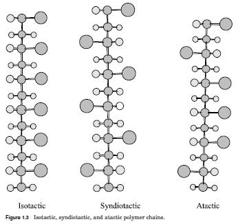
Acetal polymers are formed from the polymerization of formaldehyde.
They are also known by the name polyoxymethylenes (POM). Polymers
prepared from formaldehyde were studied by Staudinger in the 1920s,
but thermally stable materials were not introduced until the 1950s
when DuPont developed Delrin.1 Homopolymers are prepared from
very pure formaldehyde by anionic polymerization, as shown in Fig.
1.4. Amines and the soluble salts of alkali metals catalyze the reaction.2
The polymer formed is insoluble and is removed as the reaction proceeds.
Thermal degradation of the acetal resin occurs by unzipping
with the release of formaldhyde. The thermal stability of the polymer
is increased by esterification of the hydroxyl ends with acetic anhydride.
An alternative method to improve the thermal stability is copoly
merization with a second monomer such as ethylene oxide. The copolymer
is prepared by cationic methods.3 This was developed by Celanese
and marketed under the tradename Celcon. Hostaform is another
copolymer marketed by Hoescht. The presence of the second monomer
reduces the tendency for the polymer to degrade by unzipping.4
There are four processes for the thermal degradation of acetal
resins. The first is thermal or base-catalyzed depolymerization from
the chain, resulting in the release of formaldehyde. End capping the
polymer chain will reduce this tendency. The second is oxidative
attack at random positions, again leading to depolymerization. The
use of antioxidants will reduce this degradation mechanism.
Copolymerization is also helpful. The third mechanism is cleavage of
the acetal linkage by acids. It is, therefore, important not to process
acetals in equipment used for polyvinyl chloride (PVC), unless it has
been cleaned, due to the possible presence of traces of HCl. The fourth
degradation mechanism is thermal depolymerization at temperatures
above 270°C. It is important that processing temperatures remain
below this temperature to avoid degradation of the polymer.5
Acetals are highly crystalline, typically 75% crystalline, with a melting
point of 180°C.6 Compared to polyethylene (PE), the chains pack
closer together because of the shorter C O bond. As a result, the polymer
has a higher melting point. It is also harder than PE. The high
degree of crystallinity imparts good solvent resistance to acetal polymers.
The polymer is essentially linear with molecular weights (Mn) in
the range of 20,000 to 110,000.7
Acetal resins are strong and stiff thermoplastics with good fatigue
properties and dimensional stability. They also have a low coefficient
of friction and good heat resistance.8 Acetal resins are considered similar
to nylons, but are better in fatigue, creep, stiffness, and water
resistance.9 Acetal resins do not, however, have the creep resistance of
polycarbonate. As mentioned previously, acetal resins have excellent
solvent resistance with no organic solvents found below 70°C, however,
swelling may occur in some solvents. Acetal resins are susceptible
to strong acids and alkalis, as well as oxidizing agents. Although the
C O bond is polar, it is balanced and much less polar than the carbonyl
group present in nylon. As a result, acetal resins have relatively
low water absorption. The small amount of moisture absorbed may
cause swelling and dimensional changes, but will not degrade the polymer
by hydrolysis.10 The effects of moisture are considerably less dramatic
than for nylon polymers. Ultraviolet light may cause
degradation, which can be reduced by the addition of carbon black. The
copolymers generally have similar properties, but the homopolymer
may have slightly better mechanical properties, and higher melting
point, but poorer thermal stability and poorer alkali resistance.11
Along with both homopolymers and copolymers, there are also filled
materials (glass, fluoropolymer, aramid fiber, and other fillers), toughened
grades, and ultraviolet (UV) stabilized grades.12 Blends of acetal
with polyurethane elastomers show improved toughness and are available
commercially.
Acetal resins are available for injection molding, blow molding, and
extrusion. During processing it is important to avoid overheating or the
production of formaldehyde may cause serious pressure buildup. The
polymer should be purged from the machine before shutdown to avoid
excessive heating during startup.13 Acetal resins should be stored in a
dry place. The apparent viscosity of acetal resins is less dependent on
shear stress and temperature than polyolefins, but the melt has low
elasticity and melt strength. The low melt strength is a problem for
blow molding applications. For blow molding applications, copolymers
with branched structures are available. Crystallization occurs rapidly
with postmold shrinkage complete within 48 h of molding. Because of
the rapid crystallization it is difficult to obtain clear films.14
The market demand for acetal resins in the United States and
Canada was 368 million pounds in 1997.15 Applications for acetal
resins include gears, rollers, plumbing components, pump parts, fan
blades, blow-molded aerosol containers, and molded sprockets and
chains. They are often used as direct replacements for metal. Most of
the acetal resins are processed by injection molding, with the remainder
used in extruded sheet and rod. Their low coefficient of friction
make acetal resins good for bearings.16
Modern
Plastics
Handbook
Modern Plastics
and
Charles A. Harper Editor in Chief
Technology Seminars, Inc.
Lutherville, Maryland
McGraw-Hill
New York San Francisco Washington, D.C. Auckland Bogotá
Caracas Lisbon London Madrid Mexico City Milan
Montreal New Delhi San Juan Singapore
Sydney Tokyo Toronto
High-Molybdenum Alloys13

High-molybdenum stainless and nickel alloys are welded with an overmatching filler metal.
This is necessary to maintain corrosion resistance in the weld metal at least equal to the
base metal. The reason is that molybdenum and chromium segregate as the weld metal
solidifies from the melt. This leaves local areas with high and low molybdenum content.
Pitting corrosion can start in the low-Mo areas, with the pits eventually growing even into
metal with high molybdenum content. This occurs in alloys ranging from 316L to C-276,
for the most part being more severe at higher alloy contents
This matter began to receive attention when the 6% Mo stainless steels came on the
market. If any of these 6% Mo grades are welded without filler metal, the result is a weld
bead that may be as low as 3% Mo in areas. The end result can be that this weld has only
the pitting corrosion resistance of 317L stainless. In the case of tubular products autogenously
welded in production, a high-temperature anneal is used to homogenize the metal. In addition,
a small amount of nitrogen, 3–5%, is added to the torch gas. Fabrications of thin sheet,
which cannot be annealed after welding, should have this nitrogen addition to minimize the
loss of corrosion. Even so, because thin-sheet welds solidify more quickly, the segregation
is less severe.
In normal fabrication of a 6% Mo grade, alloy 625 (ERNiCrMo-3) filler metal is used.
The weld metal contains 9% Mo. After welding, segregation causes some areas to have as
little as 6% Mo. The result is that the alloy 625 weld bead has approximately the same
corrosion resistance as the 6% Mo base metal. Higher alloy weld fillers, such as ERNiCrMo-
10 or ERNiCrMo-14, may also be used, though the benefit may be more theoretical than
real. ERNiCrMo-4 is not suggested, as it has 5% less chromium than does AL-6XN, for
example. Since the mid-1980s nearly all of the 6% Mo alloy fabrications have been made,
and put into service, using a 9% Mo weld filler.
ERNiCrMo-3 weld filler is widely available and is appropriate for welding lower alloys
such as 317L, 317LMN, and 904L for chloride service. The problem of reduced weld bead
corrosion resistance from molybdenum and chromium segregation exists with most of the
13–16% Mo nickel alloys as well. Filler 686 CPT (ERNiCrMo-14) does appear to be markedly
less susceptible to this effect than other high-molybdenum alloys.
STAINLESS STEELS
James Kelly
Rochester, Michigan
Mechanical Engineers’ Handbook: Materials and Mechanical Design, Volume 1, Third Edition.
Edited by Myer Kutz
2006 by John Wiley & Sons, Inc.
Line types and thicknesses

The standard ISO 128:1982 gives 10 line types that are defined A to
K (excluding the letter I). The table in Figure 3.4 shows these lines.
The line types are 'thick', 'thin', 'continuous', 'straight', 'curved',
'zigzag', 'discontinuous dotted' and 'discontinuous chain dotted'.
Each line type has clear meanings on the drawing and mixing up
one type with another type is the equivalent of spelling something
incorrectly in an essay.
The line thickness categories 'thick' and 'thin' (sometimes called
'wide' and 'narrow') should be in the proportion 1:2. However,
although the proportion needs to apply in all cases, the individual
line thicknesses will vary depending upon the type, size and scale of
the drawing used. The standard ISO 128:1982 states that the
thickness of the 'thick' or 'wide' line should be chosen according to
the size and type of the drawing from the following range: 0,18;
0,25; 0,35; 0,5; 0,7; 1; 1,4 and 2mm. However, in a direct contradiction
of this the standard ISO 128-24:1999 states that the thicknesses
should be 0,25; 0,35; 0,5; 0,7; 1; 1,4 and 2mm. Thus
confusion reigns and the reader needs to beware! With reference to
the table in Figure 3.4, the A-K line types are as follows.
The ISO type 'A' lines are thick, straight and continuous, as shown
in Figure 3.5. They are used for visible edges, visible outlines, crests
of screw threads, limit of length of full thread and section viewing
lines. The examples of all these can be seen in the vice assembly
detailed drawings. These are by far the most common of the lines
types since they define the artefact.
The ISO type 'B' lines are thin, straight and continuous, as shown
in Figure 3.6. They are used for dimension and extension lines,
leader lines, cross hatching, outlines of revolved sections, short
centre lines, thread routes and symmetry ('equals') signs.
Engineering Drawing for Manufacture
by Brian Griffiths
· ISBN: 185718033X
· Pub. Date: February 2003
· Publisher: Elsevier Science & Technology Books
Manufacturing Data and Knowledge
THE MECHANICAL
SYSTEMS
DESIGN
HANDBOOK
Modeling, Measurement,
and Control
OSITA D. I. NWOKAH
YILDIRIM HURMUZLU
Southern Methodist University
Dallas, Texas
CRC PRESS
Boca Raton London New York Washington, D.C.
BASIC LINKAGE CONCEPTS

Kinematic Elements
A linkage is composed of rigid-body members, or links, connected to one another by
rigid kinematic elements, or pairs. The nature of those connections as well as the
shape of the links determines the kinematic properties of the linkage.
Although many kinematic pairs are conceivable and most do physically exist,
only four have general practical use for linkages. In Fig. 3.1, the four cases are seen
to include two with one degree of freedom (f = 1), one with f = 2, and one with f = 3.
Single-degree-of-freedom pairs constitute joints in planar linkages or spatial linkages.
The cylindrical and spherical joints are useful only in spatial linkages.
The links which connect these kinematic pairs are usually binary (two connections)
but may be tertiary (three connections) or even more.A commonly used tertiary
link is the bell crank familiar to most machine designers. Since our primary
interest in most linkages is to provide a particular output for a prescribed input, we
deal with closed kinematic chains, examples of which are depicted in Fig. 3.2. Considerable
work is now under way on robotics, which are basically open chains. Here
we restrict ourselves to the closed-loop type. Note that many complex linkages can
be created by compounding the simple four-bar linkage.This may not always be necessary
once the design concepts of this chapter are applied.
Richard E. Gustavson
Technical Staff Member
The Charles Stark Draper Laboratory, Inc.
Cambridge,Massachusetts
Downloaded from Digital Engineering Library @ McGraw-Hill (www.digitalengineeringlibrary.com)
Technical Staff Member
The Charles Stark Draper Laboratory, Inc.
Cambridge,Massachusetts
Downloaded from Digital Engineering Library @ McGraw-Hill (www.digitalengineeringlibrary.com)
Standard Test Method for Water and Sediment in Crude Oil by Centrifuge Method

This standard is issued under the fixed designation D 96; the number immediately following the designation indicates the year of original
adoption or, in the case of revision, the year of last revision. A number in parentheses indicates the year of last reapproval. A superscript
epsilon (e) indicates an editorial change since the last revision or reapproval.
This method has been approved by the sponsoring committees and accepted by the Cooperating Societies in accordance with established
procedures.
This test method has been adopted for use by government agencies to replace Method 3003 of Federal Test Method Standard No. 791b.
Annex A1 is under revision and will be included in subsequent revisions to this standard.
1. Scope
1.1 This test method covers the centrifuge method for
determining sediment and water in crude oil during field
custody transfers. This test method may not always provide the
most accurate results, but it is considered the most practical
method for field determination of sediment and water. When a
higher degree of accuracy is required, the laboratory procedure
described in Test Methods D 4006, D 4377 or D 473 should be
used.
NOTE 1—Water by distillation and sediment by extraction are considered
the most accurate methods of determining sediment and water in
crude oils. As such, these methods should be employed to resolve
differences in results from variations of this procedure or between this
procedure and other methods, or in the case of a dispute between parties.
1.2 This standard does not purport to address all of the
safety concerns, if any, associated with its use. It is the
responsibility of the user of this standard to establish appropriate
safety and health practices and determine the applicability
of regulatory limitations prior to use.
2. Referenced Documents
2.1 ASTM Standards:
D 235 Specification for Mineral Spirits (Petroleum Spirits)
(Hydrocarbon Drycleaning Spirits)2
D 362 Specification for Industrial Grade Toluene2
D 473 Test Method for Sediment in Crude Oils and Fuel
Oils by the Extraction Method3
D 846 Specification for Ten-Degree Xylene2
D 1209 Test Method for Color of Clear Liquids (Platinum-
Cobalt Scale)2
D 3699 Specification for Kerosine4
D 4006 Test Method for Water in Crude Oil by Distillation4
D 4057 Practice for Manual Sampling of Petroleum and
Petroleum Products4
D 4177 Practice for Automatic Sampling of Petroleum and
Petroleum Products4
D 4377 Test Method for Water in Crude Oils by Potentiometric
Karl Fischer Titration4
E 1 Specification for ASTM Thermometers5
E 542 Practice for Calibration of Volumetric Ware6
2.2 API Standards:7
Manual of Petroleum Measurement Standards
Chapter 8, Sampling Petroleum and Petroleum Products
Chapter 10, Sediment and Water
3. Summary of Test Method
3.1 Known volumes of crude oil and solvent (water saturated
if required) are placed in a centrifuge tube and heated to
60°C 6 3°C (140°F 6 5°F). After centrifugation, the volume
of the sediment-and-water layer at the bottom of the tube is
read.
NOTE 2—It has been observed that for some waxy crude oils, temperatures
of 71°C (160°F) or higher may be required to melt the wax crystals
completely so that they are not measured as sediment. If temperatures
higher than 60°C (140°F) are necessary to eliminate this problem, they
may be used with the consent of the parties involved. If water saturation
of the solvent is required, it must be done at the same temperature.
4. Significance and Use
4.1 A determination of sediment and water content is
required to determine accurately the net volumes of crude oil
involved in sales, taxation, exchanges, inventories, and custody
transfers. An excessive amount of sediment and water in crud.
---------------------
1 This test method is under the jurisdiction of Committee D-2 on Petroleum
Products and Lubricants and is the direct responsibility of Subcommittee
D02.02.OB on Sediment and Water (Joint ASTM-JP).
Current edition approved March 25, 1988. Published December 1988. Originally
published as D 96 – 63T. Last previous edition D 96 – 73 (1984).e1
2 Annual Book of ASTM Standards, Vol 06.04.
3 Annual Book of ASTM Standards, Vol 05.01.
4 Annual Book of ASTM Standards, Vol 05.02.
5 Annual Book of ASTM Standards, Vol 14.03.
6 Annual Book of ASTM Standards, Vol 14.02.
7 Available from American Petroleum Institute, 1220 L St., Northwest, Washington,
DC 20005.
An American National Standard
British Standard 4385
American Association State
Highway Transportation Standard
AASHTO No. T55
AMERICAN SOCIETY FOR TESTING AND MATERIALS
100 Barr Harbor Dr., West Conshohocken, PA 19428
Reprinted from the Annual Book of ASTM Standards. Copyright ASTM


