Drawing Number

The drawing number is used for part identification and to ease storage and retrieval of the drawing and the produced parts. While there is no set way to assign part numbers, common systems are nonsignificant, significant, or some combination of the two previous systems.
Nonsignificant numbering systems are most preferred because no prior knowledge of significance is required.
Significant numbering systems could be used for commonly purchased items like fasteners. For example, the part number for a washer could include the inside diameter, outside diameters, thickness, material, and plating.
A combination of nonsignificant and significant numbering systems may use sections of the numbers in a hierarchical manner. For example, the last three digits could be the number assigned to the part (001, 002, 003, etc.). This would be nonsignificant. The remaining numbers could be significant: two numbers could be the model variation, the next two numbers could be the model number, and the next two could be the series number while the last two could be the project number. Many other possibilities exist.
Dimensioning and Tolerancing
Handbook
Paul J. Drake, Jr.
McGraw-Hill
New York San Francisco Washington , D.C. Auckland Bogata
Caracas Lisbon London Madrid Mexico City Milan
Montreal New Delhi San Juan Singapore
Sydney Tokyo Toronto


  • Read more........
  • DEFINING PLASTIC PART REQUIREMENTS -2

    Weather Resistance Temperature, moisture, and UV sun exposure affect plastic parts’ properties and appearance. The end-use of a product determines the type of weather resistance required. For instance, external automotive parts such as mirror housings must withstand continuous outdoor exposure and perform in the full range of weather conditions. Additionally, heat gain from sun on dark surfaces may raise the upper temperature requirement considerably higher than maximum expected temperatures. Conversely, your requirements may be less severe if your part is exposed to weather elements only occasionally. For example, outdoor Christmas decorations and other seasonal products may only have to satisfy the requirements for their specific, limited exposure. Radiation A variety of artificial sources — such as fluorescent lights, high-intensity discharge lamps, and gamma sterilization units — emit radiation that can yellow and/or degrade many plastics. If your part will be exposed to a radiation source, consider painting it, or specifying a UV-stabilized resin. Appearance Aesthetic requirements can entail many material and part-design issues. For example, a need for transparency greatly reduces the number of potential plastics, especially if the part needs high clarity. Color may also play an important role. Plastics must often match the color of other materials used in parts of an assembly. Some applications require the plastic part to weather at the same rate as other materials in an assembly. Engineering Polymers Part and Mold Design THERMOPLASTICS A Design Guide Bayer Corporation • 100 Bayer Road • Pittsburgh http://www.bayer.com/polymers-usa

    Oblique projection

    In oblique projection, the object is aligned such that one face (the front face) is parallel to the picture plane. The projection lines are still parallel but they are not perpendicular to the picture plane.
    This produces a view of the object that is 3D. The front face is a true view (see Figure 2.7). It has the advantage that features of the front face can be drawn exactly as they are, with no distortion. The receding faces can be drawn at any angle that is convenient for illustrating the shape of the object and its features. The front face will be a true view, and it is best to make this one the most complicated of the faces. This makes life easier! Most oblique projections are drawn at an angle of 45 ~ and at this angle the foreshortening is 50%. This is called a Cabinet projection. This is because of its use in the furniture industry. If the 45 ~ angle is used and there is no foreshortening it is called a Cavalier projection. The problem with Cavalier projection is that, because there is no foreshortening, it looks peculiar and distorted. Thus, Cabinet projection is the preferred method for constructing an oblique projection.
    An oblique drawing of the bearing bracket in Cabinet projection is shown in Figure 2.8. For convenience, the front view with circles was chosen as the true front view. This means that the circles are true circles and therefore easy to draw. The method of construction for oblique projection is similar to the method described above for isometric projection except that the angles are not 30 ~ but 45 ~ .
    Enclosing rectangles are again used and transposed onto the 45 ~ oblique planes using 50% foreshortening.


    Engineering Drawing for Manufacture
    by Brian Griffiths
    Publisher: Elsevier Science & Technology Books


  • Read more........
  • Critical Role of Computers in Modern Manufacturing

    A number of steps are involved in manufacturing a part from its conceptualization to production. They include product design, process planning, production system design, and process control. Computers are used extensively in all these stages to make the entire process easier and faster. Potential benefits of using computers in manufacturing include reduced costs and lead times in all engineering design stages, improved quality and accuracy, minimization of errors and their duplication, more efficient analysis tool, and accurate control and monitoring of the machines/processes, etc. Some of the applications of computers in manufacturing are shown in Figure 1.5. In computeraided design (CAD), computers are used in the design and analysis of the products and processes. They play a critical role in reducing lead time and cost at the design stages of the products/process. Also, computers may be utilized to plan, manage, and control the operations of a manufacturing system: computer-aided manufacturing (CAM) (Bedworth, Handerson, and Wolfe, 1991). In CAM, computers are either used directly to control and monitor the machines/processes (in real-time) or used off-line to support manufacturing operations such as computer-aided process planning (CAPP) or planning of required materials. At higher levels, computers are utilized in support of management. They play a critical role in all stages of decision making and control of financial operations by processing and analyzing data and reporting the results (management information systems, MIS) (Hollingam, 1987). Computers facilitate integration of CAD, CAM, and MIS (computer-integrated manufacturing, CIM) (Vajpayee, 1995) (see Figure 1.5). They provide an effective communication interface among engineers, design, management, production workers, and project groups to improve efficiency and productivity of the entire system. THE MECHANICAL SYSTEMS DESIGN HANDBOOK Modeling, Measurement, and Control OSITA D. I. NWOKAH YILDIRIM HURMUZLU Southern Methodist University Dallas, Texas CRC PRESS Boca Raton London New York Washington, D.C.

    FORMING - DRILLING - REAMING - BORING

    FORMING
    Forming is the process of turning convex, or concave or of any irregular shape. Form turning may be accomplished by the following methods:
    1.using a forming tool
    2.combining cross-land longitudinal feed.
    3.tracing or coping a template.

    DRILLING
    Drilling is the operation of producing a cylindrical hole in a work piece by the rotating cutting edge of a cutter known as drill.

    REAMING
    Reaming is a process of finishing and sizing a hole, which has been drilled or bored. The tool used is called reamer, which has multiple cutting edges. The reamer is held on tailstock spindle, either direct or through a drill chucks and is held stationary while the work is revolved at a very low speed. The feed varies from 0.5 to 2mm per revolution.

    BORING
    Boring is the operation of enlarging and truing a hole produced by drilling, punching, casting or forging.
    1.The work is revolved in a chuck or a faceplate and the tool, which is fitted to the tool post, is fed in to the work.
    2.The work is clamped on the carriage and a boring bar holding the tool is supported between the centers and made to revolve.
    fr. NTTF ( NETTUR TECHNICAL TRAINING FOUNDATION)


  • Read more........
  • Torsion

    A bar is under torsional stress when it is held fast at one end, and a force acts at the other end to twist the bar. In a round bar (Fig. 4.9) with a constant force acting, the straight-line ab becomes the helix ad, and a radial line in the cross-section, ob, moves to the position ad. The angle bad remains constant while the angle bod increases with the length of the bar. Each cross section of the bar tends to shear off the one adjacent to it, and in any cross section the shearing stress at any point is normal to a radial line drawn through the point. Within the shearing proportional limit, a radial line of the cross section remains straight after the twisting force has been applied, and the unit shearing stress at any point is proportional to its distance from the axis.
    The twisting moment, T, is equal to the product of the resultant, P, of the twisting forces, multiplied by its distance from the axis, p. Resisting moment, T,, in torsion, is equal to the sum of the moments of the unit
    shearing stresses acting along a cross section with respect to the axis of the bar. If d A is an elementary area of the section at a distance of z units from the axis of a circular shaft [Fig. 4.9 (b)], and c is the distance from
    the axis to the outside of the cross section where the unit shearing stress is Z, then the unit shearing stress acting on dA is (ZZ/C) dA, its moment with respect to the axis is (zz2/c) dA, and the sum of all the moments
    of the unit shearing stresses on the cross section is f (rz2/c) dA. In this expression the factor fz2 dA is the polar moment of inertia of the section with respect to the axis. Denoting this by J the resisting moment may be written zJ/c.
    The polar moment of inertia of a surface about an axis through its center of gravity and perpendicular to the surface is the sum of the products obtained by multiplying each elementary area by the square of its distance from the center of gravity of its surface; it is equal to the sum of the moments of inertia taken with respect to two axes in the plane of the surface at right angles to each other passing through the center of gravity section of a round shaft.
    The analysis of torsional shearing stress distribution along noncircular cross sections of bars under torsion is complex. By drawing two lines at right angles through the center of gravity of a section before twisting,
    and observing the angular distortion after twisting, it has been found from many experiments that in noncircular sections the shearing unit stresses are not proportional to their distances from the axis. Thus in a rectangular bar there is no shearing stress at the comers of the sections, and the stress at the middle of the wide side is greater than at the middle of the narrow side. In an elliptical bar the shearing stress is greater along the flat side than at the round side.

    Plastics
    Engineered
    Product
    Design
    Dominick Rosato and
    Donald Rosato
    ELSEVIER


  • Read more........
  • Insulated Runners

    The insulated runner system (Figure 41) allows the molten polymer to flow into the runner, and then cool to form an insulating layer of solid plastic along the walls of the runner. The insulating layer reduces the diameter of the runner and helps maintain the temperature of the molten portion of the melt as it awaits the next shot. The insulated runner system should be designed so that, while the runner volume does not exceed the cavity volume, all of the molten polymer in the runners is injected into the mold during each shot. This full consumption is necessary to prevent excess build-up of the insulating skin and to minimize any drop in melt temperature. The many advantages of insulated runner systems, compared with conventional runner systems, include: • Less sensitivity to the requirements for balanced runners. • Reduction in material shear. • More consistent volume of polymer per part. • Faster molding cycles. • Elimination of runner scrap – less regrind. • Improved part finish. • Decreased tool wear. However, the insulated runner system also has disadvantages. The increased level of technology required to manufacture and operate the mold results in: • Generally more complicated mold design. • Generally higher mold costs. • More difficult start-up procedures until running correctly. • Possible thermal degradation of the polymer melt. • More difficult color changes. • Higher maintenance costs. Product and Mold Design d9b604f1c18a4896b020a210866ec775.

    Standards ANSI ISO

    Standards If a machinist in a machine shop in a remote location is required to make a part for a US-built commercial aircraft, he or she must understand the drawings. This requires worldwide, standardized drafting practices. Many countries support a national standards development effort in addition to international participation. In the United States, the two groups of standards that are most influential are developed by the standards development bodies administered by the American National Standards Institute (ANSI) and the International Organization for Standardization (ISO). See Chapter 6 for a comparison of US and ISO standards. ANSI The ANSI administers the guidelines for standards creation in the United States. The American Society of Mechanical Engineers sponsors the development of the Y14 series of standards. The 26 standards in the series cover most facets of engineering drawings and related documents. Many of the concepts about how to read an engineering drawing presented in this chapter come from these standards. In addition to the Y14 series of standards, the complete library should also possess the B89 Dimensional Measurement standards series and the B46 Surface Texture standard. ISO The ISO, created in 1946, helped provide a structure to rebuild the world economy (primarily Europe) after World War II. Even though the United States has only one vote in international standards development, the US continues to propose many of the concepts presented in the ISO drafting standards. Dimensioning and Tolerancing Handbook Paul J. Drake, Jr. McGraw-Hill New York San Francisco Washington , D.C. Auckland Bogata Caracas Lisbon London Madrid Mexico City Milan Montreal New Delhi San Juan Singapore Sydney Tokyo Toronto

    Linear and angular dimensioning

    The latest ISO standard concerned with dimensioning is ISO 129"1985. However, it is known that a new one is soon to be published which is ISO 129 Part 1 (the author sits on BSI/ISO committees and has seen the draft new standard). It has been through all the committee approval stages and has been passed for publication. However, it is being held back, awaiting the approval of a Part 2 so that they can be published together. The BSI estimates the publication date will be 2003, hence it will be ISO 129-1:2003.
    There have been versions prior to 1985 and each has defined slightly different dimensioning conventions. Needless to say, the 2003 convention gives a slightly different convention to the 1985 one! Throughout this section, the 2003 convention will be presented so that readers are prepared for the latest version. Figure 4.3 shows a hypothetical spool valve that is defined by 14 dimensions in which 12 are linear and two angular. The valve is shown using the ISO principles of line thickness described in
    Chapter 3. Note that the valve outline uses the ISO type 'A' thickness whereas the other lines (including the dimension lines) are the ISO type 'B' thin lines. The outline thus has more prominence than the other lines and hence the valve tends to jump out of the drawing page and into the eye of the reader. The valve dimensions
    follow the dimensioning convention laid down in the future ISO 129-1:2003 standard. Tolerances have been left off the figure for convenience. In this case there are two datum features. The first is the left-hand annular face of the largest cylindrical diameter, i.e. the face with the 30 ~ chamfer. Horizontal dimensions associated
    with this datum face use a terminator in the form of a small circle.
    The other datum feature is the centre rotational axis of the spool valve represented by the chain dotted line. All the extension lines touch the outline of the spool valve. The dimension values are normally placed parallel to their dimension line, near the middle, above and clear of it. Dimension values should be placed in such a
    way that they are not crossed or separated by any other line.

    Engineering Drawing for Manufacture
    by Brian Griffiths
    Publisher: Elsevier Science & Technology Books


  • Read more........
  • Cold Slug Wells

    At all runner intersections, the primary runner should overrun the  secondary runner by a minimum distance equal to one diameter, as shown in Figure 39. This produces a feature known as a melt trap or cold slug well. Cold slug wells improve the flow of the polymer by catching the colder, higher-viscosity polymer moving at the forefront of the molten mass and allowing the following, hot, lower-viscosity polymer to flow more readily into the mold-cavity.
    The cold slug well thus prevents a mass of cold material from entering the cavity and adversely affecting the final properties of the finished part.


  • READ MORE.......

  • The "shaft basis" and the "hole basis' system of fits

    In all the examples given above, the discussion has been concerning 'shafts' and 'holes'. It should be remembered that this does not necessarily apply to shafts and holes. These are just generic termsthat mean anything that fits inside anything else. However, whatever the case, it is often the case that either the shaft or the hole is the easier to produce. For  example, if they are cylindrical, the shaft will be the more easily produced in that one turning tool can produce an infinite number of shaft diameters. This is not the case with the cylindrical hole in that each hole size will be dependent on a single drill or reamer.

    The right-hand diagram in Figure 5.10 shows the situation in which the shaft is the more difficult of the two to produce and this is referred to as the 'shaft basis' system of fits. In this case the system of fits is used in which the required clearances or interferences are obtained by associating holes of various tolerance classes with shafts of a single tolerance class. Alternatively if the shaft is the easier part to produce then the hole basis system of fits is used. This is a system of fits in which the required clearances and interferences are obtained by associating shafts of various tolerance classes with holes of a single tolerance class. In the case of the shaft basis system the shaft is kept constant and the interference or clearance functional situation is achieved by manipulating the hole. If the hole-based system is used, the opposite is the case. The appropriate use of each
    system for functional performance situation is thus made easier for the manufacturer.


  • READ MORE.......


  • Engineering Drawing for Manufacture
    by Brian Griffiths
    Publisher: Elsevier Science & Technology Books


    Forging Simulation

    According to the difficulties which have just been presented, the design problem often results in trial and error. It is both time and money  consuming, as the shapes of the dies are complex, difficult, and expensive to produce. In order to lower these costs, several simulation strategies have been developed to replace the actual trials. Easy to form model materials such as lead, plasticine [52], and wax [64] can be substituted to the current metal, making it possible to reduce the forming force. These materials, and more particularly plasticine and wax which are more widely used today, exhibit nearly the same behavior as the metal under hot isothermal conditions. One of the main restriction of this approach is the temperature dependency of the model materials, which is quite different from the behavior of the metal.

    However, for most of the processes, the forging is so fast that the heat exchanges with the dies is small and that the heat generated by the material deformation is not enough to significantly modify the material flow. Thus, this technique provides an easy way to study the material flow, to predict the major defects such as folds [42] and insufficient pressure in the die details, and to estimate the forging force. Moreover, it is possible to study the material deformation and the fibering by mixing model materials of several colors. With some mechanical models, the total strain can be computed out of these pieces of information [52]. By mixing model materials with different properties, or by adding some other components, the behavior of the model material can be slightly adjusted to the behavior of the studied metal. As often for metal forming processes, the friction phenomenon is difficult to simulate. However, some kind of model materials for the lubricants can be proposed.

    The main shortcoming of this simulation approach is that although the dies can be produced into a less expensive material and without heat treatment, they are as complex as the actual process, which requires significant time and energy to produce them. Moreover, as has been mentioned earlier, the thermal effects cannot be taken into account.

    Nowadays, the numerical simulation provides much faster results as the toolings are only virtually designed. Moreover, these results are more accurate and more varied, such as the flow at different times of the process, the velocity field, the strain, the strain rates, the stresses, the temperature, the tool wear, and the tool deformation. Several softwares have been marketed, such as the well spread FORGE2 and DEFORM2D (initially called ALPID), [47] for axisymmetrical and plane strain problems.
    They are actual tools for designers and their industrial use is ever increasing. Indeed, they make it easy to quickly find the main shortcomings of the studied design, and then to test several modifications to improve it. For expensive safety parts, or for very large single parts, they also provide a quality insurance as they give an estimation of the mechanical characteristics of the part which should otherwise be obtained by destructive testing. Regarding the true three-dimensional problems, automatic remeshing difficulties, as well as  computational time and memory requirements, have long hindered the industrial use of these softwares. 

    Nowadays, both the software and hardware progresses have made these computations possible. They are used in forging companies, for instance to understand the development of a fold and test whether a new preform design can remove it [22]. The tool shape discretization required for the numerical simulation, often a finite element mesh of the tool surface by triangles, can almost directly be obtained from the CAD design. It reduces to rather insignificant times the specific numerical design required by the finite element simulation. FORGE3 and DEFORM3D [66] are such available softwares


  • READ MORE.......


  • COMPUTER-AIDED DESIGN,
    ENGINEERING, AND MANUFACTURING
    Systems Techniques And Applications
    VOLUME V I
    Editor
    CORNELIUS LEONDES
    Boca Raton London New York Washington, D.C.
    CRC Press
    MANUFACTURING
    SYSTEMS PROCESSES


    Facing, KNURLING, FILING

    Facing
    Facing is the operation of machining the ends of a piece of work to produce a flat surface square with the axis. This is also used to cut the work to the required length. The operation involves feeding the tool perpendicular to the axis of rotation of the work piece.

    KNURLING
    Knurling is the process of embossing a diamond shaped pattern on the surface of a work piece. The purpose of knurling is to provide an effective gripping surface on a work piece to prevent it from slipping when operated by hand. The tool is held rigidly on the tool post and the rollers are pressed against the revolving work piece to squeeze the metal against the multiple cutting edges, producing depressions in a regular pattern on the surface of the work piece.

    FILING
    Filing is the finishing operation performed after turning. This is done in a lathe to remove burrs, shape corners, and feed marks on a work piece and also to bring it to the size by removing very small amount of metal. The speed is usually twice that of turning. The file should b slowly moved forward so that the work may pass 2 to 3 revolutions during the cutting stroke. During the return stroke the pressure is relived but an end wise feeding movement is given, overlapping the previous cut.


  • READ MORE.......


  • fr. NTTF ( NETTUR TECHNICAL TRAINING FOUNDATION)


    ISO tolerance ranges

    Tolerance bands need to be defined which can be related to functional
    performance and manufacturing processes. The ISO has published tolerance ranges to help designers. Examples of these tolerance ranges are shown in Figure 5.4. This table is only a selection from the full table given in ISO 286-2:1988. The full range goes up to IT18 and 3m nominal size. The tolerance ranges are defined by 'IT' ranges as shown in the  diagram from IT1 to IT11. The range given in the ISO standard is significantly more complicated than the extract in Figure 5.4. It should be noted that the range increases as the IT number gets larger and the range increases as the nominal size increases. The latter is fairly logical in
    that one would expect the tolerance range to be larger as the diameter increases because the precision that can be achieved must be relative. The ranges were not chosen out of the blue but empirically derived and based on the fact that the relationship between manufacturing errors and basic size can be approximated by a parabolic function.


  • READ MORE.......


  • Engineering Drawing for Manufacture
    by Brian Griffiths
    · ISBN: 185718033X
    · Publisher: Elsevier Science & Technology Books


    State of the Art of Design Techniques for Non-Steady-State Metal Forming Processes

    Basic Design Techniques
    The forging problem can be summarized as to find the best process design, which makes it possible to form the required part. We do not consider the preliminary problem of dressing. We assume that the
    forged part has already been designed out of the shape of the final part, which will often be obtained after machining. The problem is just to design a deformation path for the material in order to obtain a prescribed shape with satisfactory properties and for the lower cost. Of course, the deformation paths are not unique, and that can include several forging  operations. So the problem is to find the best shapes of the preforming tools, the best forming temperatures (both the initial temperature of the billet and the temperature of the dies), the best forging velocities, the best lubricant and lubrication conditions, etc.
    The optimality conditions regard several parameters which may depend on the process itself. However,
    most of the time, the optimal forging design has to obtain the right final part without major defects such as folds, to minimize the number of operations, to minimize the size of the initial billet, to reduce the maximum forging force during the operations, and so on.
    This is a complex design problem as often the material flow is three-dimensional and difficult to foresee. It is not possible to simplify it into a less complex problem which could be more easily studied. In fact, in this area, there is a deep lack of simple mathematical models. Just a few problems can be analytically solved, such as the upsetting of a cylinder (or a bar) between flat dies without friction. Although it provides some interesting tendencies, it is far too simple to be useful for the design of a close-die forging process. So, the industrial practice was mainly based on thumb rules and empirical knowledge which have been obtained either by actual experiences, by reduced scale or simulation experiments, or by more complex mathematical models [51, 2].
    Some approximated models and methods have been developed, for instance by Chamouard [11], in order to predict the filling of the forging dies and the forging force. Unfortunately, they are not easy to use. In order to bring them within the reach of these persons, recently, the Chamouard’s approach has been incorporated into computer software [56]. However, according to the present computer performances and the restricting hypothesis of such models, this is probably not the most efficient and modern way to simulate the process, as we shall see.
    As a matter of fact, all the proposed methods are restricted to two-dimensional (axisymmetrical or plane strain approximation) problems. For complex three-dimensional flows, the 3D problem has first to be decomposed into several 2D plane strain problems (see Fig. 5.1), which is both not easy and not always possible.


  • READ MORE.......


  • COMPUTER-AIDED DESIGN,
    ENGINEERING, AND MANUFACTURING
    Systems Techniques And Applications
    VOLUME
    V I
    Editor
    CORNELIUS LEONDES
    Boca Raton London New York Washington, D.C.
    CRC Press
    MANUFACTURING
    SYSTEMS PROCESSES


    Step formation and release of products in blow Blow Molding

    Mold is opened, after a long-parison which flows through the side pieces, mold will close, followed by movement of the blades are cut off above the parison mold. After the parison mold stuck on the move, which was originally under the tip of the die head is now under blowpin, Then blowpin down to blow the parison to expand the shape of the cavity.
    At the top of the mold are part of a hardened steel, serves as the foundation adjacent to the cutting of the parison excess of the mold.
    The foundation is called the striker plate cutting, cutter was called the outing blowpin end of the sleeve is attached.

    Product formation steps and expenditures.
    1.Mold catch parison, the knife cut off the excess parison upper mold, then mold moves downward move the position of blowpin.
    2.Blowpin move down to blow the parison into a product, which is then followed by cooling the product in the mold.
    3.The process of cooling, the mold opens and moves towards the bottom to catch the parison die head again. It is equivalent blowpin move, which goes along with the product because the mouth(which is due to shrinkage after cooling) blowpin gripping end.
    4.Blowpin rose steadily up to the mouth blowpin held back by the nest, regardless of the end blowpin and fall. Meanwhile parison mold was arrested and will move down blowpin next to the blowing process.


  • READ MORE.......


  • Thread Cutting operation

    In a thread cutting operation the first step is to remove the excess material from the work piece to make its diameter equal to the major diameter of the screw thread. Change gears of correct size are then fitted to the end of the bed between the spindle and the lead screw. The shape or form of the thread depend s on the shape of the cutting tool to be used. In a metric thread, the included angle of the cutting edge should be ground exactly 60o. The top of the tool nose should be set at the same height as the centre of the work piece. A thread tool gauge is usually used against the turned surface to check the cutting tool so that each face of the tool may be equally inclined to the center line of the work piece.
    The speed of the spindle is reduced by one half to one-fourth of the speed required for turning according to the type of the material being machined, and the half-nut is then engaged. The depth of cut which usually varies from 0.05 to 0.2 mm is applied by advancing the tool perpendicular at to the axis of the work or at an angle equal to one-half of the angle of the thread, and 30o in the case of metric thread, by swiveling the compound rest.


  • READ MORE.......


  • fr. NTTF ( NETTUR TECHNICAL TRAINING FOUNDATION)


    Recommended Design for Molded-in Threads

    Molded-in threads can be designed into parts made of engineering thermoplastic
    resins. Threads always should have radiused roots and should not have feather
    edges – to avoid stress concentrations.
    Figure 35 shows examples of good design for molded-in external and internal threads. For additional information on molded-in threads, see page 105. Threads also form undercuts and should be treated as such when the part is being removed from the mold i.e., by provision of unscrewing mechanisms, collapsible cores, etc. Every effort should be made to locate external
    threads on the parting line of the mold where economics and mold reliability are
    most favorable.


  • READ MORE.......


  • Product and Mold Design


    Dimensioning principles

    A drawing should provide a complete specification of  the component to ensure that the design intent can be met at all stages of manufacture. Dimensions specifying features of size, position, location, geometric control and surface texture must be defined and appear on the drawing once only. It should not be necessary for the craftsman either to scale the drawing or to deduce dimensions by the subtraction or addition of other dimensions. Double dimensioning is also not acceptable.

    Theoretically any component can be analysed and divided into a number of standard common geometrical shapes such as cubes, prisms, cylinders, parts of cones, etc. The circular hole in Fig. 14.1 can be considered as a cylinder through the plate. Dimensioning a component is the means of specifying the design intent in the manufacture and verification of the finished part.

    A solid block with a circular hole in it is shown in Fig. 14.1 and to establish the exact shape of the item we require to know the dimensions which govern its length, height and thickness, also the diameter and depth of the hole and its position in relation to the surface of the block. The axis of the hole is shown at the intersection of two centre lines positioned from the left hand side and the bottom of the block and these two surfaces have been taken as datums. The length and height have also been measured from these surfaces separately and this is a very important point as errors may become cumulative and this is discussed later in the chapter.

    Dimensioning therefore, should be undertaken with a view to defining the shape or form and overall size
    of the component carefully, also the sizes and positions of the various features, such as holes, counterbores,
    tappings, etc., from the necessary datum planes or axes.
    The completed engineering drawing should also include sufficient information for the manufacture of the part and this involves the addition of notes regarding the materials used, tolerances of size, limits and fits, surface finishes, the number of parts required and any further comments which result from a consideration of the use to which the completed component will be put. For example, the part could be used in sub-assembly
    and notes would then make reference to associated drawings or general assemblies.

    British Standard 8888 covers all the ISO rules applicable to dimensioning and, if these are adhered to, it is reasonably easy to produce a drawing to a good professional standard.
    1 Dimension and projection lines are narrow continuous lines 0.35 mm thick, if possible, clearly placed outside the outline of the drawing. As previously mentioned, the drawing outline is depicted with wide lines of 0.7 mm thick. The drawing outline will then be clearly defined and in contrast with the dimensioning system.
    2 The projection lines should not touch the drawing but a small gap should be left, about 2 to 3 mm, depending on the size of the drawing. The projection lines should then continue for the same distance past the dimension line.
    3 Arrowheads should be approximately triangular, must be of uniform size and shape and in every case touch the dimension line to which they refer. Arrowheads drawn manually should be filled in. Arrowheads drawn by machine need not be filled in.
    4 Bearing in mind the size of the actual dimensions and the fact that there may be two numbers together
    where limits of size are quoted, then adequate space must be left between rows of dimensions and a
    spacing of about 12 mm is recommended.
    5 Centre lines must never be used as dimension lines but must be left clear and distinct. They can be extended, however, when used in the role of projection lines.
    6 Dimensions are quoted in millimetres to the minimum number of significant figures. For example, 19 and not 19.0. In the case of a decimal dimension, always use a nought before the decimal marker, which might not be noticed on a drawing print that has poor line definition. We write 0,4 and not .4. It should be stated here that on metric drawings the decimal marker is a comma positioned on the base line between the figures, for example, 5,2 but never 5·2 with a decimal point midway.
    7 To enable dimensions to be read clearly, figures are placed so that they can be read from the bottom of the drawing, or by turning the drawing in a clockwise direction, so that they can be read from the right hand side.
    8 Leader lines are used to indicate where specific indications apply. The leader line to the hole is directed towards the centre point but terminates at the circumference in an arrow. A leader line for a part number terminates in a dot within the outline of the component. The gauge plate here is assumed to be part number six of a set of inspection gauges.


  • READ MORE.......


  • Manual of
    Engineering Drawing
    Second edition
    Colin H Simmons
    I.Eng, FIED, Mem ASME.
    Engineering Standards Consultant
    Member of BS. & ISO Committees dealing with
    Technical Product Documentation specifications
    Formerly Standards Engineer, Lucas CAV.
    Dennis E Maguire
    CEng. MIMechE, Mem ASME, R.Eng.Des, MIED
    Design Consultant
    Formerly Senior Lecturer, Mechanical and
    Production Engineering Department, Southall College
    of Technology
    City & Guilds International Chief Examiner in
    Engineering Drawing


    ECCENTRIC TURNING, CHAMFERING, THREAD CUTTING LATHE

    If a cylindrical work piece has two separate axis of rotation one being out of centre to the other, the work piece is termed eccentric and turning of different surfaces of the wok piece is known as eccentric turning. The shaft is first mounted on its true centre and the part forming the journal is turned. The job is then remounted on the offset centre and the eccentric surfaces are machined.

    CHAMFERING
    Chamfering is the operation of beveling the extreme end of a work piece this done to remove the burrs, to protect the end of the work piece from being damaged and to have a better look. The operation may be preformed after knurling, rough turning, boring, drilling or thread cutting. Chamfering is an essential operation after thread cutting so that the nut may pass freely on the threaded work piece.

    THREAD CUTTING:
    Thread cutting is the most important operation performed in lathe.
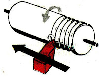
    The principle of thread cutting is to produce a helical groove on a cylindrical or conical surface by feeding the tool longitudinally when job is revolved between centers or by a chuck. The longitudinal feed should be equal to the pitch of thread to be cut per revolution of the work piece. The lead screw of the lathe, through which the saddle receives its traversing motion, has a definite pitch. A definite ratio between the longitudinal feed and rotation of the head stock spindle should therefore be found out so that the relative speeds of rotation of the work and the lead screw will result in the cutting of a screw of the desired pitch. This is affected by change gears arranged between the spindle and lead screw or by the change gear mechanism or feed box used in a modern lathe where it provides a wider range of feed and the speed ratio can be easily and quickly changed.


  • READ MORE.......


  • fr. NTTF ( NETTUR TECHNICAL TRAINING FOUNDATION)


    CORNERS Injection moulding

    When the ideas of correct and uniform wall thickness are put into practice the result is a plastics part composed of relatively thin
    surfaces. The way in which these surfaces are joined is equally vital to the quality of a moulded part.
    Walls usually meet at right angles, at the corners of a box for example. Where the box walls meet the base, the angle will generally be slightly more than 90 degrees because of a draft angle on the walls. The easiest way, and the worst, to join the walls is to bring them together with sharp corners inside and out. This causes two problems.
    The first difficulty is that the increase in thickness at the corner breaks the rule of uniform wall thickness. The maximum thickness at a sharp corner is about 1.4
    times the nominal wall thickness. The result is a longer cooling time accompanied by a risk of sink marks and warping due to differential shrinkage.
    The other problem is even more serious.
    Sharp corners concentrate stress and greatly increase the risk of the part failing in service. This is true for all materials and especially so for plastics. Plastics are said to be notch-sensitive because of their marked tendency to break at sharp corners. This happens because the stress concentration at the corner is sufficient to initiate a microscopic crack which spreads right through the wall to cause total failure of the part. Sharp internal corners and notches are the single most common cause of mechanical failure in moulded parts.
    The answer is to radius the internal corner, but what size should the radius be? Most walls approximate to a classical cantilever structure so it is possible to calculate stress concentration factors for a range of wall thicknesses and radii. The resulting graph shows that the stress concentration increases very sharply when the ratio of radius to wall thickness falls below 0.4. So the internal radius (r) should be at least half the wall thickness (t) and preferably be in the range 0.6 to 0.75 times wall thickness.
    If the inner corner is radiussed and the outer corner left sharp, there is still a thick point at the corner. For an internal radius of 0.6t, the maximum thickness increases to about 1.7 times the wall thickness. We can put this right by adding a radius to the outside corner as well. The outside radius should be equal to the inside radius plus the wall thickness. This results in a constant wall thickness


    DESIGNER’S NOTEBOOK
    Avoid sharp internal corners.
    Internal radii should be at least 0.5 and preferably 0.6 to 0.75 times the wall thickness.
    Keep corner wall thickness as close as possible to the nominal wall thickness. Ideally, external radii should be equal to the internal radii plus the wall thickness.


  • READ MORE.......


  • DESIGN GUIDES for PLASTICS
    Clive Maier, Econology Ltd
    pdg
    Plastics Design Group - Plastics Consultancy Network
    British Plastics Federation


    CLASSIFICATION OF DRAWING

    Machine Drawing
    It is pertaining to machine parts or components. It is presented through a number of orthographic views, so that the size and shape of the  component is fully understood. Part drawings and assembly drawings belong to this classification. An example of a machine drawing is given in Fig. 1.1.


    Production Drawing
    A production drawing, also referred to as working drawing, should furnish all the dimensions, limits and special finishing processes such as heat treatment, honing, lapping, surface finish, etc., to guide the craftsman on the shop floor in producing the component. The title should also mention the material used for the product, number of parts required for the assembled unit, etc.
    Since a craftsman will ordinarily make one component at a time, it is advisable to prepare the production drawing of each component on a separate sheet. However, in some cases the drawings of related omponents may be given on the same sheet. Figure 1.2 represents an example of a production drawing.

    Part drawing
    Component or part drawing is a detailed drawing of a component to facilitate its manufacture. All the  principles of orthographic projection and the technique of graphic representation must be followed to communicate the details in a part drawing. A part drawing with production details is rightly called as a production drawing or working drawing.

    Assembly drawing
    A drawing that shows the various parts of a machine in their correct working locations is an assembly drawing (Fig. 1.3). There are several types of such drawings

  • READ MORE.......


  • MACHINE DRAWING
    Dr.K.L.Narayana
    Dr.P.Kannaiah
    K.Venkata Reddy
    www.newagepublisher.com
    NEW AGE INTERNATIONAL (P) LIMITED, PUBLISHER


    Labels

    2d (1) 3D (1) ABG (1) agen JNE (1) almari (1) Alufoil (1) Aluminum Foil (1) anilox roll (1) apartemen (1) Atom (1) autocad (1) backdrop logo (1) bagian dalam (1) bangunan (1) batu alam (1) berkualitas (1) bermutu (1) berpengalaman (1) bertingkat (1) birdview (1) black and white (1) botol plastik (1) cafe (1) classic (1) coklat (1) cold rolled sheet (1) Computer To Plate (1) Consumer Understanding (1) control movement (1) counter (1) CTP (1) denah berwarna (1) denah kantor (1) desain (1) desain cuci mobil (1) desain kamar (1) desain produk (1) design (1) Design and Function (1) design meja (1) Design restaurant (1) design rumah (1) di daerah (1) dinding bata (1) dining (1) Duromer (1) Electrons (1) etnik (1) factors (1) flexo packaging (1) flexo printing (1) food (1) furniture (1) gallus (1) gambar (1) gaya modern (1) gloss (1) grc kotak (1) Halftone (1) hanya 550 ribu (1) harga murah (1) hasil cepat (1) hotel (1) industrial (1) injection (1) Injection Mold (1) ink (1) inovatif (1) install (1) interior (1) interior rumah (1) jasa gambar rumah (1) jasa 3d (1) jasa arsitek (1) jasa desain (1) jasa desain 3d (1) jasa design (1) jasa designer (1) jasa gambar (1) kamar tidur (1) kamar tidur anak (1) kampus (1) karaoke (1) kawasan (1) kawasan industri (1) kemasan (1) kerja di rumah (1) kitchen set (1) kontemporer (1) kosan (1) kost (1) krem (1) laci (1) lamination (1) lithography (1) living room (1) livingroom (1) lounge (1) Luscher MultiDX (1) masterplan (1) matt (1) meja kerja (1) metalworking (1) mewah (1) minimalis (1) minimalist (1) modern (1) mold (1) molding (1) Monomer (1) murah (1) murah. (1) Neutron (1) nuansa remaja (1) offset (1) online design (1) open ceiling (1) outdoor (1) overprint (1) pabrik (1) pantai (1) pencahayaan (1) perumahan (1) pesan desain (1) pesan desain toko (1) plug (1) Polimer (1) Polyaddition (1) Polycondensation (1) Polymerization (1) Polystyrene (1) printing ink (1) Product Creation (1) product function (1) produk katalog (1) Protons (1) Raster Image Processor (1) register (1) rendering (1) resepsionis (1) responsibility (1) resto industrial (1) RIP (1) Rotary (1) ruang kantor (1) ruang keluarga (1) ruang kerja (1) ruang tamu (1) ruang tunggu (1) ruko (1) rumah (1) rumah hook (1) rumah susun (1) rumah tropis (1) scandinavian (1) screen printing (1) sederhana (1) sempoa (1) setup (1) simple sederhana (1) specifications (1) spring (1) steel (1) Struktur Plastik (1) suspension (1) sweet home (1) taman (1) tampak (1) tampak rumah (1) Technological Change (1) terbaru (1) termurah (1) toko aksesoris (1) toko asesoris (1) trapping (1) two cavity (1) unscrewing (1) use (1) uv varnish (1) via online (1) website (1)